Lens assembly and imaging device

a technology of assembly and lens, applied in the direction of mountings, instruments, camera body details, etc., can solve the problems of affecting the shooting effect of the camera, affecting the quality of the image, and the space required for enlargement of the lens frame, so as to achieve the effect of comfortable shooting operation

Inactive Publication Date: 2009-10-01
FUJI PHOTO OPTICAL CO LTD
View PDF2 Cites 12 Cited by
  • Summary
  • Abstract
  • Description
  • Claims
  • Application Information

AI Technical Summary

Benefits of technology

[0024]According to the imaging device, since the lens assembly having the structure in which the vapor condensation is prevented from occurring is ...

Problems solved by technology

However, even when the O ring is used to prevent the entry of the water, since the lens located at the part nearest to the object side directly receives the influence of an external temperature change, if a space is formed in a rear surface of the lens, a problem still arises that a vapor condensation is liable to occur in the rear surface side of the lens.
However, in a structure that the nitrogen gas is sealed in the lens fr...

Method used


Image

  • Lens assembly and imaging device
  • Lens assembly and imaging device
  • Lens assembly and imaging device

Examples


Embodiment Construction

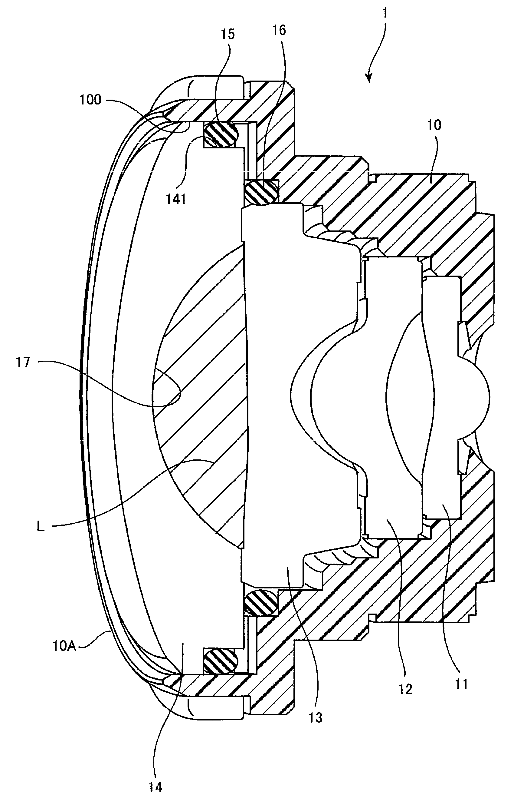
[0028]According to an exemplary embodiment of the present invention, it is possible to provide a lens assembly having the structure in which when a space is formed in the rear surface side of the lens located at the part nearest to the object side, the vapor condensation hardly occurs in the part in contact with the space and a dustproof function, and to provide an imaging device having the lens assembly.

[0029]Now, an exemplary embodiment of the present invention will be described below.

[0030]FIG. 1 is a diagram showing the structure of a lens assembly 1 of an exemplary embodiment of the present invention.

[0031]FIG. 1 shows the lens assembly 1 including four lenses 11 to 14 and a lens frame 10 with a hollow part having an object side opening and an image forming side opening and into which the four lenses 11 to 14 are inserted with their optical axes aligned.

[0032]FIG. 1 shows, in order to easily obtain a dustproof performance or a waterproof performance, an example of a structure i...


PUM


Abstract

A lens assembly is provided and includes: a plurality of lenses including a first lens located nearest to an object side of the lens assembly and a second lens located adjacent to the first lens; and a lens frame having a hollow part which includes an opening on each of an object side and an image forming side of the lens assembly and into which the plurality of lenses are inserted with their optical axes aligned. Liquid is sealed in a part between the first lens and the second lens.

Description

[0001]This application is based on and claims priority under 35 U.S.C §119 from Japanese Patent Application No. 2008-088525, filed on Mar. 28, 2008, the entire disclosure of which is herein incorporated by reference.BACKGROUND OF THE INVENTION[0002]1. Field of the Invention[0003]The present invention relates to a lens assembly having a preventing function for preventing a vapor condensation from occurring and an imaging device having the lens assembly.[0004]2. Description of Related Art[0005]Recently, motor vehicles have been equipped with cameras. Most of the cameras employ circumstances that navigation systems are popularized and display screens are provided in driver's seats to display the states of places of the dead angle for the drivers on the display screens.[0006]In such a camera to be mounted on a vehicle, since a lens located at a part nearest to the object side is arranged to be exposed to the surface of a vehicle body, a strict waterproof performance is required. Accordi...

Claims


Application Information

Patent Timeline
IPC IPC(8): G03B17/08G02B23/16
CPCG02B27/0006G02B7/021
Inventor SAKAI, YUYAKATO, KOICHI
Owner FUJI PHOTO OPTICAL CO LTD
Why Eureka
Try Eureka