Motor control device, fluid ejection device, and motor control method

a technology of motor control and fluid injection, which is applied in the direction of automatic control, electric controllers, instruments, etc., can solve the problems of paper torn up, heavy roll in the large-sheet printer, and high load when a sheet is pulled from the roll

Active Publication Date: 2009-10-01
SEIKO EPSON CORP
View PDF1 Cites 32 Cited by
  • Summary
  • Abstract
  • Description
  • Claims
  • Application Information

AI Technical Summary

Benefits of technology

[0007]An advantage of some aspects of the invention is that it provides a motor control device that can prevent a change in tension irrespective of the use of a roll when a roll paper is transported to a downstream side by driving a first motor and a second motor, a fluid ejection device, and a motor control method.
[0009]With such a configuration, when the second motor is not driven and only the first motor is driven, the relationship between the load on the first motor and the driving speed of the first motor is measured by the load measuring unit. In addition, the motor control unit provides the interpolation output based on the measurement result of the load measuring unit and the driving speed of the second motor to the first motor. Accordingly, the roll paper is not torn up and can be properly transported to the downstream side. In addition, the interpolation output is obtained from the relationship between the load on the first motor and the driving speed of the first motor. Therefore, the interpolation output is provided to the first motor while subjected to the change in the driving speed of the first motor, and the state where the change in the tension exerted on the roll paper is small can be implemented.
[0011]With such a configuration, the first and second motors are simultaneously driven. Therefore, even when a change in the speed occurs, the predetermined tension is stably given to the roll paper. Accordingly, the roll paper does not become loose. In addition, since the predetermined tension is stably exerted on the roll paper, quality of a predetermined process such as printing performed on the downstream upon transporting can be enhanced.
[0013]With such a configuration, the tension caused by a difference between the feeding distances of the first and second motors is exerted on the roll paper. Accordingly, the roll paper does not become loose. In addition, since the predetermined tension is stably exerted on the roll paper, quality of a predetermined process such as printing performed on the downstream upon transporting can be enhanced.
[0017]With such a configuration, when the second motor is not driven and only the first motor is driven, the relationship between the load on the first motor and the driving speed of the first motor is measured in the load measuring step. In addition, in the motor controlling step, the interpolation output based on the measurement result of the load measuring unit and the driving speed of the second motor is given to the first motor. Accordingly, the roll paper is not torn up and can be properly transported to the downstream side. In addition, the interpolation output is obtained from the relationship between the load on the first motor and the driving speed of the first motor. Therefore, the interpolation output is given to the first motor while subjected to the change in the driving speed of the second motor, and the state where the change in the tension exerted on the roll paper is small can be implemented.

Problems solved by technology

The roll in the large-sheet printer is heavy, and a load exerted when a sheet is pulled from the roll is high.
Accordingly, when only the PF motor is driven, there is a possibility that the paper is torn up.
In addition, for example, in the case where the weight of the roller is reduced and becomes very low, there is a possibility that tension is hardly exerted between the transport roller pair and the roll, and the paper becomes loose.
When the change in the tension as described above occurs during printing of the sheet, it may affect the print quality.

Method used


Image

  • Motor control device, fluid ejection device, and motor control method
  • Motor control device, fluid ejection device, and motor control method
  • Motor control device, fluid ejection device, and motor control method

Examples


Embodiment Construction

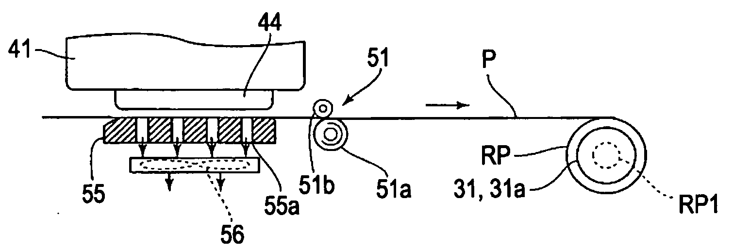
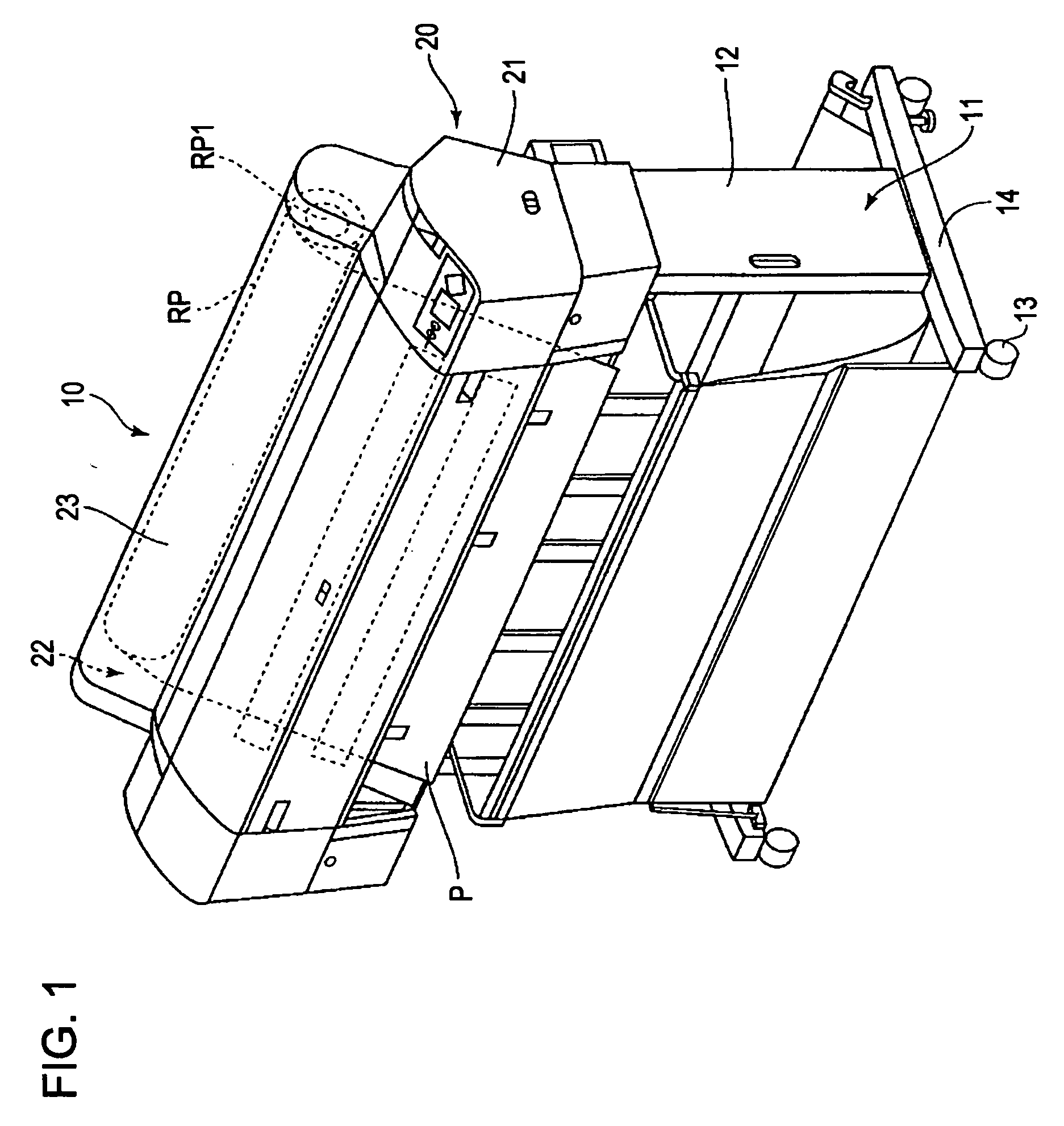
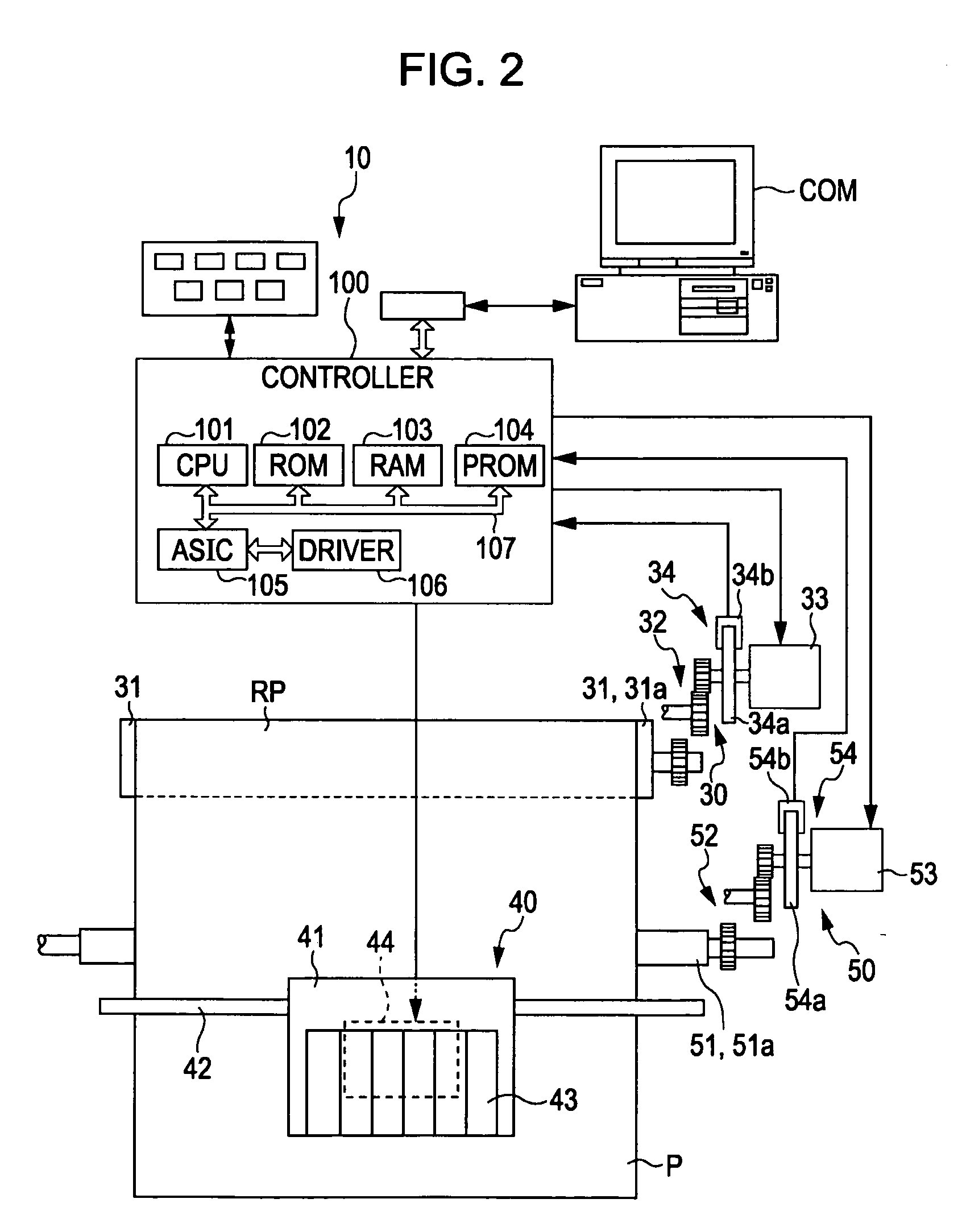
[0030]Hereinafter, a printer 10 as a fluid ejection device having a motor control device (mainly a controller 100), and a drive control method according to an embodiment of the invention will be described with reference to FIGS. 1 to 11. In addition, the printer 10 in this embodiment is a printer for printing a large sheet, for example, having an A2 or larger size in JIS standard. In addition, the printer in this embodiment is an ink jet printer, and the ink jet printer may be any apparatus employing an ejection method in which an ink is ejected for printing.

[0031]In the following description, a lower side indicates a side on which the printer 10 is provided, and an upper side indicates a side spaced from the provided side. In addition, a side for feeding a sheet P is referred to as a feed side (rear end side), and a side for ejecting the sheet P is referred to as a sheet-ejection side (front side).

Schematic Configuration of Printer 10

[0032]As illustrated in FIG. 1, the printer 10 h...


PUM


Abstract

A motor control device includes: a first motor that provides a driving force for rotating a roll on which a roll paper is wound to supply the roll paper from the roll; a second motor that provides a driving force for driving a transport driving roller which is provided on a downstream side than the roll along a supply direction of the roll paper and used for transporting the roll paper; a load measuring unit that measures a relationship between a load on the first motor and a driving speed of the first motor when the second motor is not driven and the first motor is driven; and a motor control unit that simultaneously drives the first and second motors at a certain timing, provides to the first motor an interpolation output based on the measurement result of the load measurement unit and a driving speed of the second motor during the control, and transports the roll paper to the downstream side by driving the second motor.

Description

BACKGROUND[0001]1. Technical Field[0002]The present invention relates to a motor control device, a fluid ejection device, and a motor control method.[0003]2. Related Art[0004]As an ink jet printer, there is a type of printer available for sheets having an A2 or larger size. In many cases, the large-sheet ink jet printer uses a so-called roll paper (hereinafter, the so-called roll paper that is a wound roll is referred to as a roll, and a portion pulled from the roll is referred to as a sheet) in addition to cut papers. Pulling a sheet from a roll is typically performed by a paper feed motor (PF motor). Here, the PF motor is controlled and driven by PID control. As the printer using the roll, a printer is disclosed in JP-A-2007-290866. As the printer which enables the PID control, printers are disclosed in JP-A-20006-240412, JP-A-2003-79177, and JP-A-2003-48351.[0005]The roll in the large-sheet printer is heavy, and a load exerted when a sheet is pulled from the roll is high. Accordi...

Claims


Application Information

Patent Timeline
Patent Type & Authority Applications(United States)
IPC IPC(8): B41J15/16G05B11/32
CPCB41J11/003B41J11/0085B41J13/0009B41J15/16B41J11/42
Inventor IGARASHI, HITOSHIHATADA, KENJI
Owner SEIKO EPSON CORP
Why Eureka
Try Eureka