Dental handpiece

a handpiece and dental technology, applied in the field of dental handpieces, can solve the problems of powder in the vicinity of the surface of the powder that has accumulated within the space to rise up, and achieve the effects of air, and improving the mixed condition of powder

Active Publication Date: 2009-10-01
NAKANISHI INC
View PDF3 Cites 16 Cited by
  • Summary
  • Abstract
  • Description
  • Claims
  • Application Information

AI Technical Summary

Benefits of technology

[0019]According to the present invention, in the blowout means that blows out air into a space where a powder and the air are to be mixed, a stream of air is generated along an inner circumferential surface of the space by the air that has been blown out into the space from first blowout holes formed at a tip end of the blowout means. As a result of this, within the space the powder contained is caused to rise up, thereby making it possible to improve the mixed condition of the powder and the air in the space.
[0020]Furthermore, when the amount of the contained powder is large, the air blown out of the second blowout hole formed in an outer circumferential surface of the blowout means causes the powder in the vicinity of the surface belonging to the powder accumulated within the space to rise up, thereby making it possible to improve the mixed condition of the powder and the air in the space.
[0021]On the other hand, when the remaining amount of the powder is small, the air that has been blown out of a third blowhole formed in the outer circumferential surface of the blowout means can cause the powder to rise up from a bottom part of the vessel, and also in this condition, it is possible to improve the mixed condition of the powder and the air in the space.
[0022]As described above, the mixed condition of the powder and the air in the space is improved and in addition, the mixing of the powder and the air can be promoted when the amount of the powder is large as well as when amount of the powder is small. Therefore, it is possible to stabilize the flow rate of a blown-out powder and it is possible to enable the stock of the filled powder to last longer while raising the cutting efficiency.

Problems solved by technology

As a result of this, when the amount of the contained powder is large, the air blown out of this blowout hole can cause the powder in the vicinity of the surface of the powder that has accumulated within the space to rise up.

Method used


Image

  • Dental handpiece
  • Dental handpiece
  • Dental handpiece

Examples


embodiment

[0067]The effect of the above-described constituent features was ascertained. The results are described below.

example 1

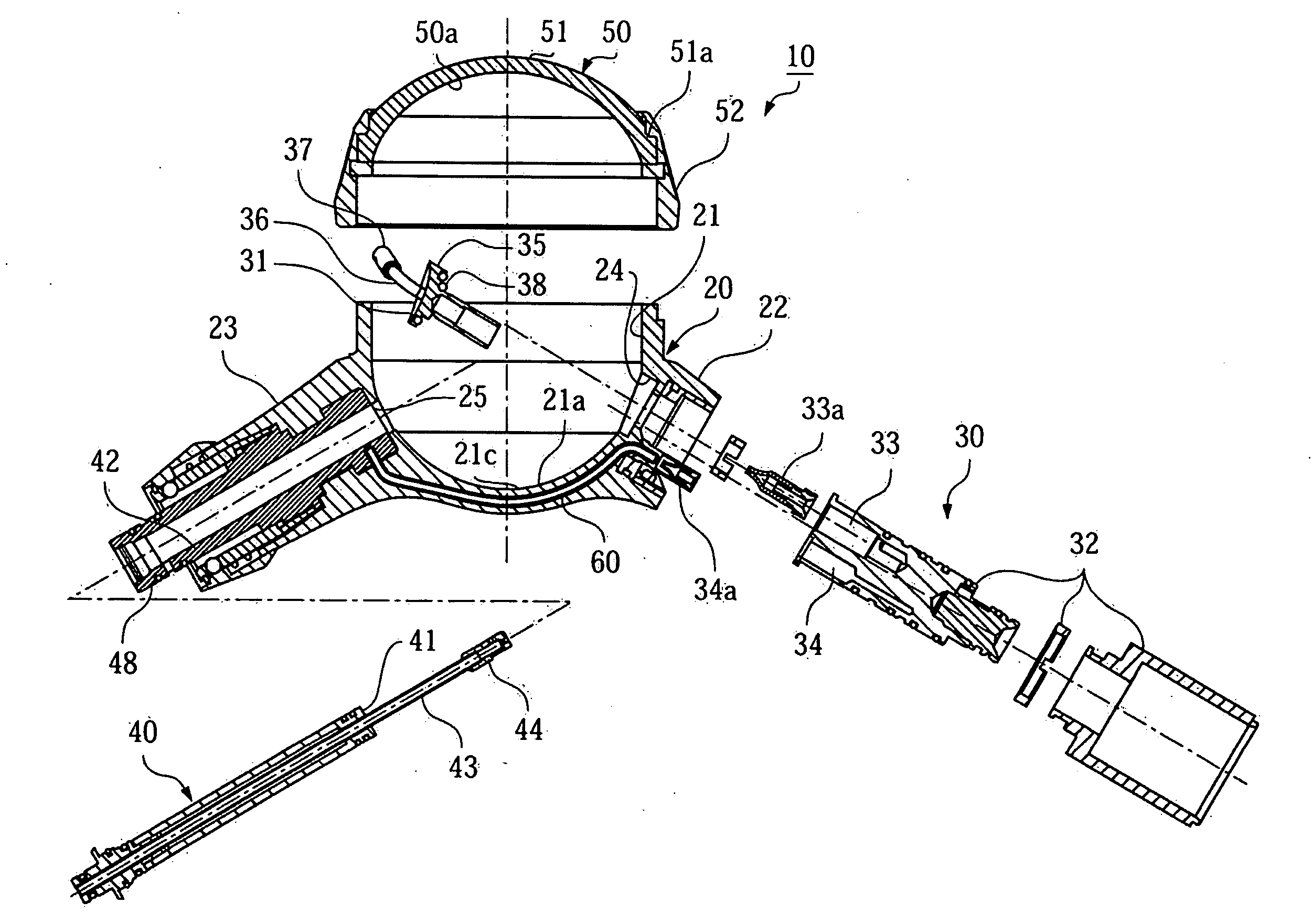
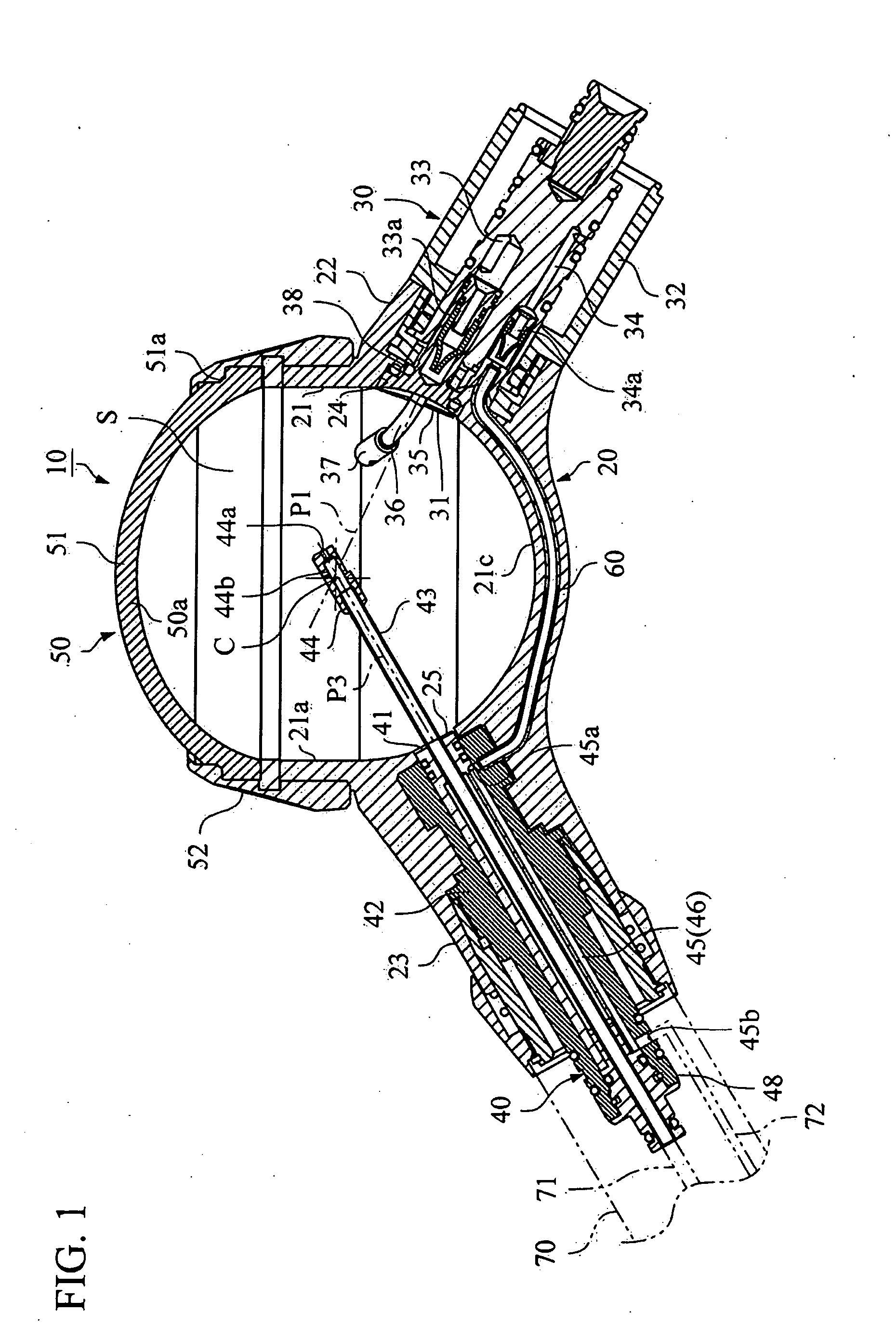
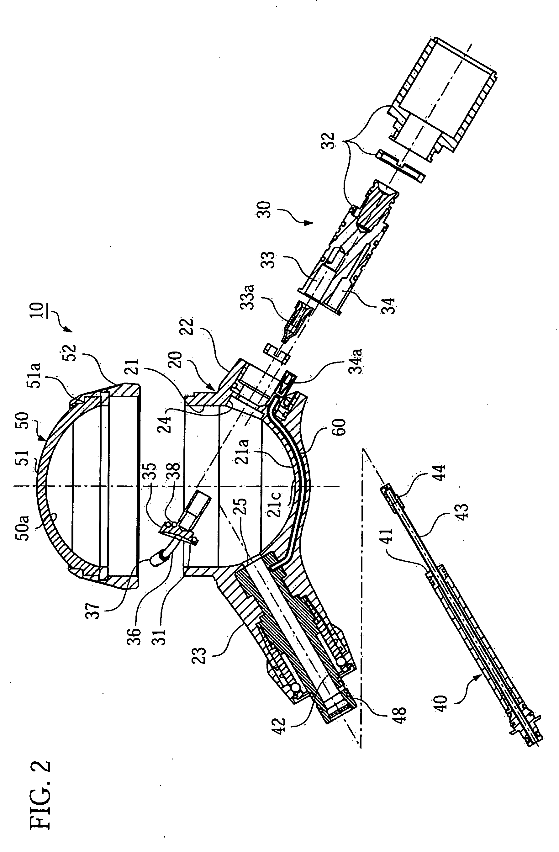
[0068]In a handpiece 10 as described above, the diameter of a space S was 36 mm, and the diameter of blowout holes 37a, 37b, 37c of a nozzle 37 was each 0.5 mm. The blowout hole 37b was formed so as to be inclined 60°, for example, to the center C side of the space S with respect to the vertical downward direction, and the blowout hole 37c was formed so as to be inclined 30°, for example, to the inner circumferential surface 21a side of a concavity 21 with respect to the vertical downward direction. And 15 g of calcium carbonate were contained in the concavity 21 as a powder, and compressed air at a pressure of 0.3 MPa was fed in.

[0069]The relationship between elapsed time and cumulative cut area was found from the remaining amount of the powder each time one minute lapsed.

example 2

[0070]For comparison, as shown in FIG. 5, a blowout hole 37a formed in a tip end portion of a nozzle 37 had a diameter of 0.4 mm, and three blowout holes 37b, 37c, 37d having a diameter of 0.4 mm were formed in the outer circumferential surface to have an angle of 60° each. By using this nozzle 37, the relationship between elapsed time and cumulative cut area was found in the same way as described above.


PUM


Abstract

Two nozzles 37 in pair are provided along an inner circumferential surface 21a of a concavity 21, air is blown out in a space from a blowout hole 37a provided at a tip end portion of the nozzle from a side where the nozzle 37 is provided aiming at an opposite side along an inner circumferential surface of the space and a powder contained in the concavity 21 is caused to rise up in the space, whereby the condition of the powder mixed with the air within the space is improved.

Description

BACKGROUND OF THE INVENTION[0001]1. Field of the Invention[0002]The present invention relates to a dental handpiece used in performing dental care by blowing a mixture of a powder and air on teeth along with water.[0003]2. Description of the Related Art[0004]There is known a dental handpiece used in blowing a mixture of a powder and air on the surfaces of teeth along with water, the powder being obtained by mixing a powder for polishing or cleaning teeth with air.[0005]Such a dental handpiece is provided, for example, with a vessel for housing a powder, an air supply path for supplying air to the interior of the vessel, a mixture conveyance path for conveying a mixture of a powder and air to a jet nozzle, and a water conveyance path for conveying the water to be blown on the surfaces of teeth along with the mixture to a jet nozzle. In this dental handpiece, a pipe in communication with the air supply path and a pipe in communication with the mixture conveyance path are each provided...

Claims


Application Information

Patent Timeline
Patent Type & Authority Applications(United States)
IPC IPC(8): A61C3/00
CPCA61C3/025A61C1/08A61C1/10
Inventor TAKAMORI, SHOICHIHARIKAE, YUSUKE
Owner NAKANISHI INC
Why Eureka
Try Eureka