Wavefront-defined radon transform

a wavefront-defined and transform technology, applied in the field of seismic data processing, can solve problems such as information loss, and achieve the effect of improving imaging quality

Active Publication Date: 2009-10-01
GEOMAGE 2003
View PDF28 Cites 24 Cited by
  • Summary
  • Abstract
  • Description
  • Claims
  • Application Information

AI Technical Summary

Benefits of technology

[0012]processing the second collection of traces to generate a seismic image of the subsurface structures at the improved imaging quality.
[0021]a signal processor, which is configured to define a Radon transform with respect to a set of wavefront parameters of the seismic waves, the transform defining a summation of amplitudes of the seismic waves over trajectories defined by the wavefront parameters, to apply the Radon transform to the first collection of traces so as to convert the first collection into a multidimensional data array that is defined as a function of at least two of the wavefront parameters, to process the multidimensional data array so as to produce a second collection of traces having an improved imaging quality with respect to the first collection, and to process the second collection of traces to generate a seismic image of the subsurface structures at the improved imaging quality.
[0022]There is also provided, in accordance with an embodiment of the present invention, a computer software product, including a computer-readable medium in which program instructions are stored, which instructions, when read by a computer, cause the computer to accept a first collection of traces corresponding to signals received over time due to reflection of seismic waves from subsurface structures, to define a Radon transform with respect to a set of wavefront parameters of the seismic waves, the transform defining a summation of amplitudes of the seismic waves over trajectories defined by the wavefront parameters, to apply the Radon transform to the first collection of traces so as to convert the first collection into a multidimensional data array that is defined as a function of at least two of the wavefront parameters, to process the multidimensional data array and re-convert the processed multidimensional data array, so as to produce a second collection of traces having an improved imaging quality with respect to the first collection, and to process the second collection of traces to generate a seismic image of the subsurface structures at the improved imaging quality.

Problems solved by technology

The assumption of hyperbolic moveout, however, is known to be an inaccurate reflection of the actual characteristics of subterranean structures, and its application leads to loss of information.

Method used


Image

  • Wavefront-defined radon transform
  • Wavefront-defined radon transform
  • Wavefront-defined radon transform

Examples


Embodiment Construction

Overview

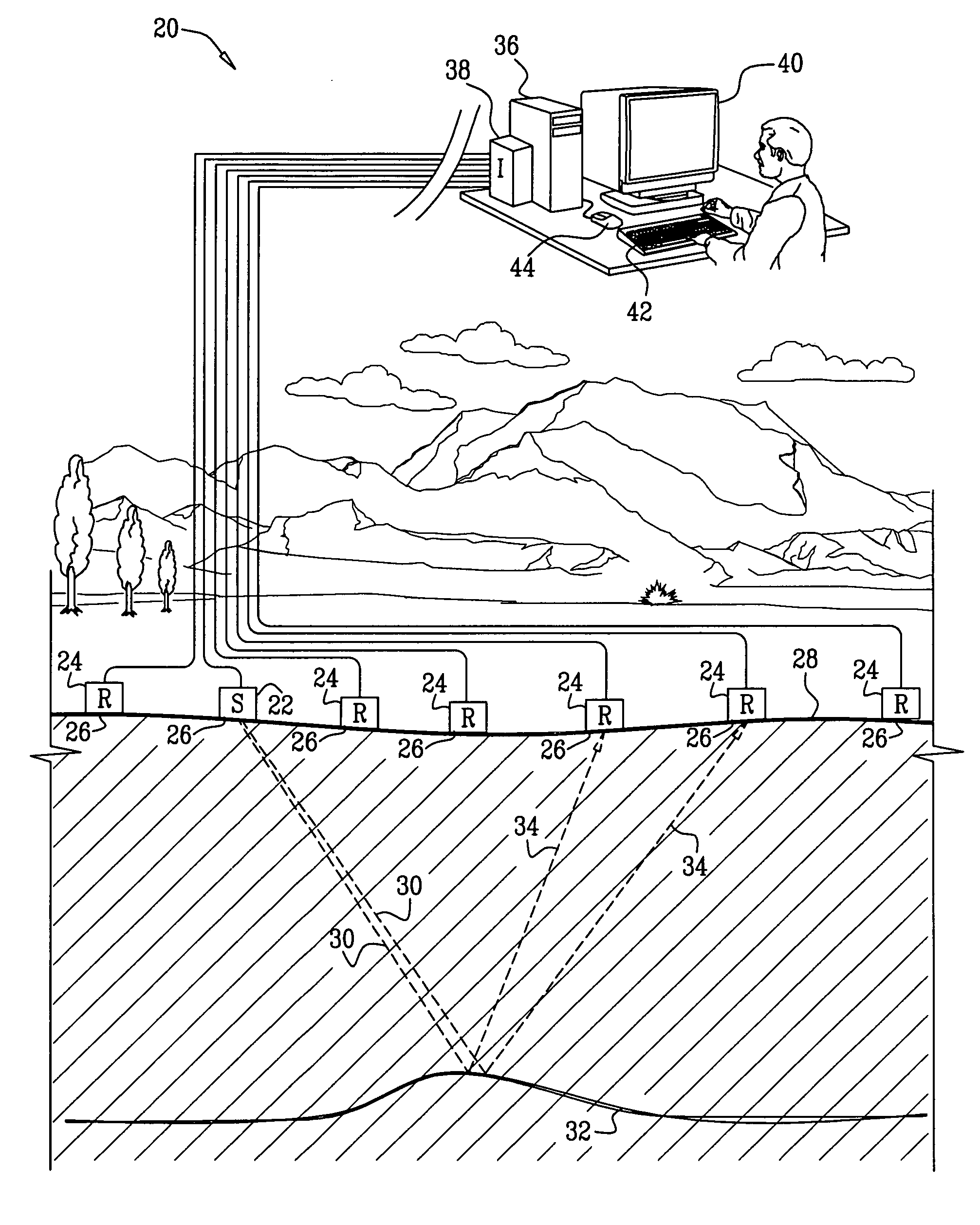
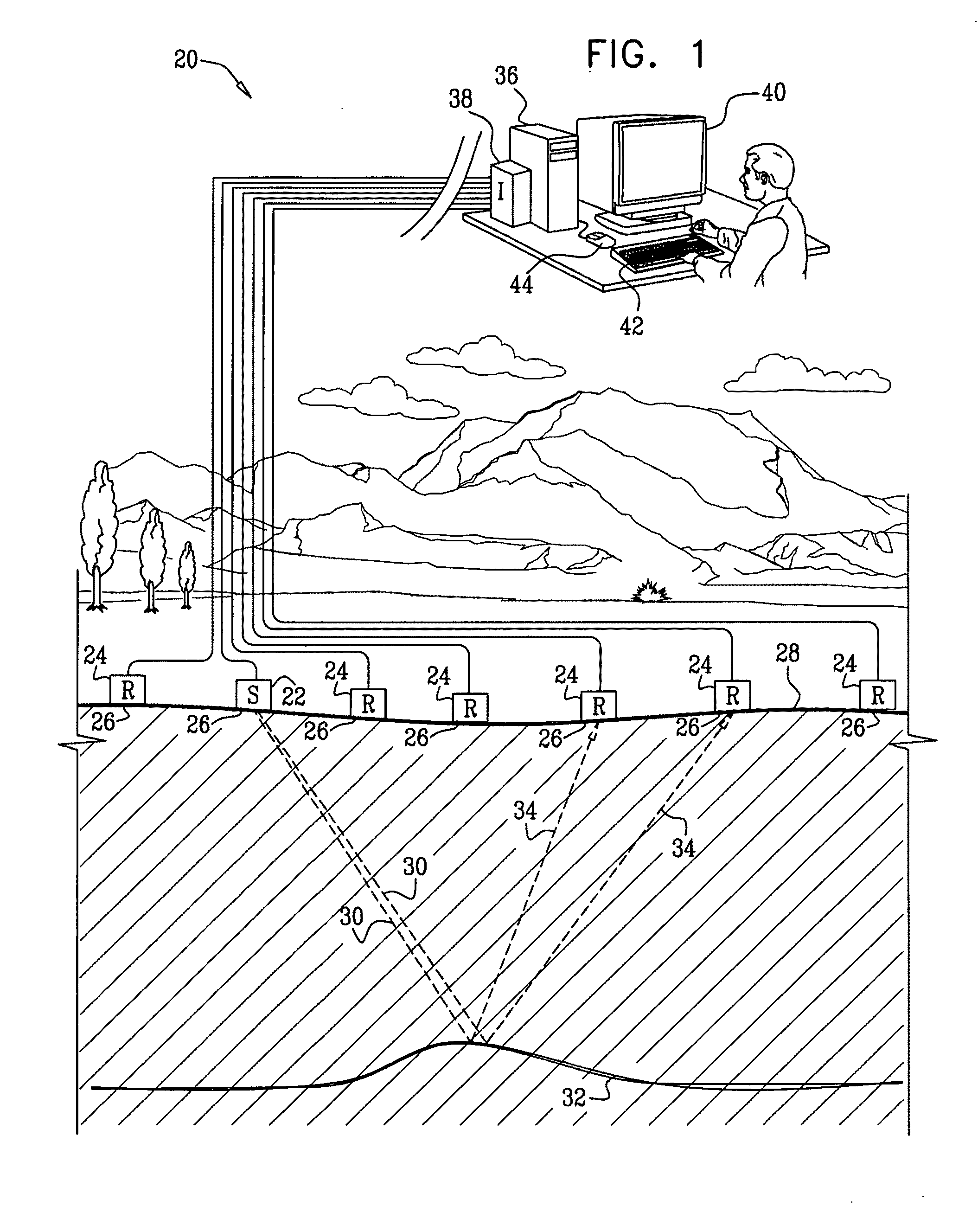
[0037]Embodiments of the present invention that are described hereinbelow provide improved methods and systems for analyzing seismic data. The methods and systems described herein apply a novel transform, referred to herein as a Wavefront-defined Radon Transform (WRT), which is expressed in terms of wavefront parameters of the seismic waves.

[0038]In some embodiments, a signal processor is provided with a collection of traces in a 2-D or 3-D time-offset domain. The set of traces is referred to as an input supergather, and may comprise common-shot gathers, common receiver gathers, CMP gathers, or a combination of different gather types. Generally, the traces in the input supergather need not be pre-selected in any way. The signal processor applies the wavefront-defined Radon transform to the input supergather, thereby converting the input supergather into a multidimensional data array that is defined as a function of at least two wavefront parameters. The wavefront parameters ...


PUM


Abstract

A computer-implemented method for processing data includes accepting a first collection of traces corresponding to signals received over time due to reflection of seismic waves from subsurface structures. A Radon transform is defined with respect to a set of wavefront parameters of the seismic waves. The transform defines a summation of amplitudes of the seismic waves over trajectories defined by the wavefront parameters.The Radon transform is applied to the first collection of traces, so as to convert the first collection into a multidimensional data array that is defined as a function of at least two of the wavefront parameters. The multidimensional data array is processed to produce a second collection of traces having an improved imaging quality with respect to the first collection. The second collection of traces is processed to generate a seismic image of the subsurface structures at the improved imaging quality.

Description

FIELD OF THE INVENTION[0001]The present invention relates generally to analyzing the structure of a medium, and specifically to processing of seismic data to analyze subterranean structures.BACKGROUND OF THE INVENTION[0002]Methods of seismic imaging that are known in the art use an array of seismic sources and receivers to acquire data regarding subsurface (i.e., subterranean) structures. Following a seismic stimulus (such as a detonation or mechanical shock) at a given source, each of the receivers produces a seismogram trace, i.e., a record of the seismic signal at the receiver as a function of time, due to reflections of the stimulus wave from the subsurface layers below the array. The traces from multiple receivers due to stimuli by sources at different locations are processed together in order to create an image of the layers.[0003]As part of the imaging process, in order to increase signal / noise ratio, multiple traces from source / receiver pairs surrounding a common midpoint (C...

Claims


Application Information

Patent Timeline
Patent Type & Authority Applications(United States)
IPC IPC(8): G01V1/34
CPCG01V1/28G01V2210/56
Inventor BERKOVITCH, ALEXANDERBELFER, IGORKAZINNIK, ROMAN
Owner GEOMAGE 2003
Why Eureka
Try Eureka