User interface providing information system topology presentation

a technology of information system and user interface, applied in the field of user interface providing information system topology presentation, can solve the problems of increasing the size and complexity of the information technology (it) system of the company, and increasing the cost of implementation

Active Publication Date: 2009-10-01
HITACHI LTD
View PDF32 Cites 86 Cited by
  • Summary
  • Abstract
  • Description
  • Claims
  • Application Information

AI Technical Summary

Benefits of technology

[0006]Exemplary embodiments of the invention provide a user interface to improve the efficiency of information system availability and improve the performance of management tasks such as monitoring of system conditions and analysis of problems within the system. Exemplary embodiments of the user interface of the invention provide superior density of displayed end-to-end topology of information systems by displaying components of the information systems in a graphical topological list view. These and other features and advantages of the present invention will become apparent to those of ordinary skill in the art in view of the following detailed description of the preferred embodiments.

Problems solved by technology

According to recent trends, information technology (IT) systems of companies are becoming ever more large and complex.
However, as mentioned above, IT systems themselves are growing rapidly, while IT budgets are typically becoming more restricted.
Thus, there is a gap emerging between manageability provided by the current management software and the size of the systems that are required to be managed.
In particular, the topological views provided by currently-available software for system monitoring or problem analyzing have become too complicated and are able to display only a small portion of the IT systems on a display screen at any one time.
Since the topology of the entire system is information necessary for an administrator to properly carry out system management for managing availability and performance of the information system, there is no currently available solution for use with large and expandable IT systems.

Method used


Image

  • User interface providing information system topology presentation
  • User interface providing information system topology presentation
  • User interface providing information system topology presentation

Examples


first embodiments

Exemplary Hardware Architecture

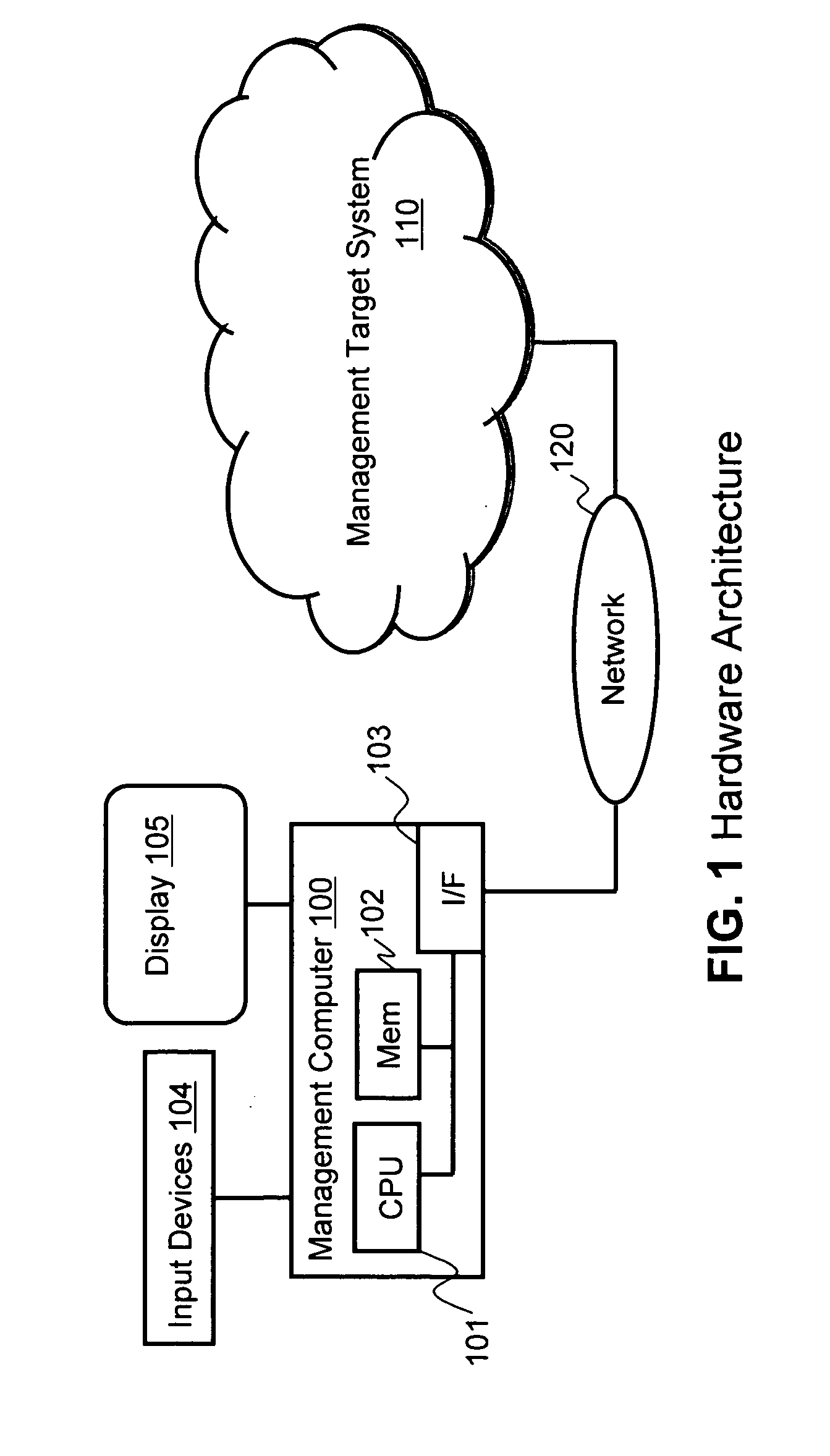
[0037]FIG. 1 illustrates an example of a hardware architecture in which the invention may be practiced. The overall system consists of a management computer 100 and a management target system 110 (i.e., an information system that is the object of management). Management computer 100 and management target system may be connected through a local or wide area network (LAN or WAN) 120, or may be otherwise connected for enabling communication.

[0038]Management computer 100 may be a server or other generic computer that includes a CPU 101, a memory and storage 102, a network interface 103, one or more input devices 104, which may include a keyboard, mouse, and the like, and a display 105, which may be a monitor or the like. Management computer 100 is typically a computer terminal used by the system administrator for managing the management target system 110. Management target system 110 is an information system composed of network switches making up one or mo...

second embodiments

[0250]In the first embodiments set forth above, the scope encompasses generating a topological representation of the entire system. However, since the invention uses a topological layout that also resembles a list or matrix based upon a lattice of rows and columns, the graphical user interface of the invention is compliant to having list-oriented functions applied to it, such as sorting of rows, filtering of items, or the like. The second embodiments described below set forth examples of methods for adopting sorting or filtering criteria, which may be specified by an administrator. Most of the components and behaviors are same as described above with respect to the first embodiments, and thus, the differences are described below.

[0251]As discussed in the first embodiments, the topology of the system displayed on the user interface with topological list view depends on what and how the connection information was listed on the joined connection data. After the connection data has been...

third embodiments

[0258]FIG. 23 illustrates another alternative embodiment of the user interface with topology presentation 4150 of the invention. In the embodiment illustrated in FIG. 23, there are four predefined columns instead of five, namely, LAN column 412, computer column 413, SAN column 414 and storage column 415. Backbone column 411 of the prior embodiments has been eliminated from this embodiment. The switches of the backbone network can either not be included in the topology display, or may be displayed in their own LAN rectangle at the bottom of the LAN column, which may have a name 431 of “Backbone” or the like. The lay out and drawing of the icons, connection lines and the other elements of the user interface 4150 illustrated in FIG. 23 may be carried out in the manner as discussed above for the previous embodiments. Other alternative embodiments will also be evident to those of skill in the art in light of the disclosure given herein.


PUM


Abstract

A user interface includes a graphical topological representation of an information system. Information is collected regarding connections between switches, storage nodes and computer nodes in the information system. Any sub networks in the system are identified based on the collected information and classified as LANs or SANs. Connections between the various components are determined, and a layout of any identified LANs, computer nodes, SANs, and storage nodes is established for generating the topological representation in the user interface. The graphical topological representation of the information system is displayed in the user interface with the LAN icons, computer node icons, SAN icons and storage node icons laid out in a matrix-like arrangement of columns and rows, such that for LANs, computer nodes, SANs and / or storage nodes that are connected to each other, the corresponding icons are located on or near a same row in the graphical topological representation.

Description

BACKGROUND OF THE INVENTION[0001]According to recent trends, information technology (IT) systems of companies are becoming ever more large and complex. For example, in some businesses, the IT system is no longer just an infrastructure of the business, but needs to act in partnership with the business to increase the value and competitiveness of the business. Furthermore, the rapid growth of IT systems is not limited to very large companies, but even mid-sized companies can now have hundreds of servers. The rapid growth of server virtualization technology is causing an acceleration of this trend.[0002]Despite the recent trends of massive growth in data centers and other IT systems, the administrators of IT organizations are still required to efficiently manage these large and complex IT systems to keep them running properly. When a problem occurs, the administrators need to recognize that there is a problem, analyze the problem and then resolve the issue as soon as possible.[0003]Typ...

Claims


Application Information

Patent Timeline
Patent Type & Authority Applications(United States)
IPC IPC(8): G06F3/048
CPCG06F9/4443H04L41/22H04L41/12G06F9/451G06F3/04817G06F3/0482G06F3/0484
Inventor MURASE, ATSUSHIMASUISHI, TETSUYAFUJITA, TAKAHIRO
Owner HITACHI LTD
Why Eureka
Try Eureka