Articulated arm coordinate measuring machine

Active Publication Date: 2009-10-08
LEICA GEOSYSTEMS AG
View PDF15 Cites 71 Cited by
  • Summary
  • Abstract
  • Description
  • Claims
  • Application Information

AI Technical Summary

Benefits of technology

[0043]According to the invention, even if the slope of the floor varies and, thus, also the cubical orientation of the articulated arm CMM in the measuring room varies, the points to be measured of an object surface can be referenced with improved accuracy compared with CMMs of the state of the art. For example, such variations of the floor of the measuring room may be caused by changing load conditions on the floor, particularly affected through a measuring person or a heavy object to be measured—like a car.

Problems solved by technology

Furthermore, a torque or a force which acts not perpendicular to the supporting surface onto the base of the articulated arm during measurements may introduce an error in case that the support and / or the base are not rigid enough.
This may happen if the counterbalance system of the arm uses spring forces for providing a balanced arm, as such a counterbalance system may introduce varying and not straight down acting forces onto the base while operating and moving the probe of the arm.

Method used


Image

  • Articulated arm coordinate measuring machine
  • Articulated arm coordinate measuring machine
  • Articulated arm coordinate measuring machine

Examples


Embodiment Construction

[0050]The principles of the embodiments described herein show the structure and operation of several examples used to illustrate the present invention. It should be understood that the drawings are diagrammatic and schematic representations of such example embodiments and, accordingly, are not limiting the scope of the present invention, nor are the drawings necessarily drawn to scale.

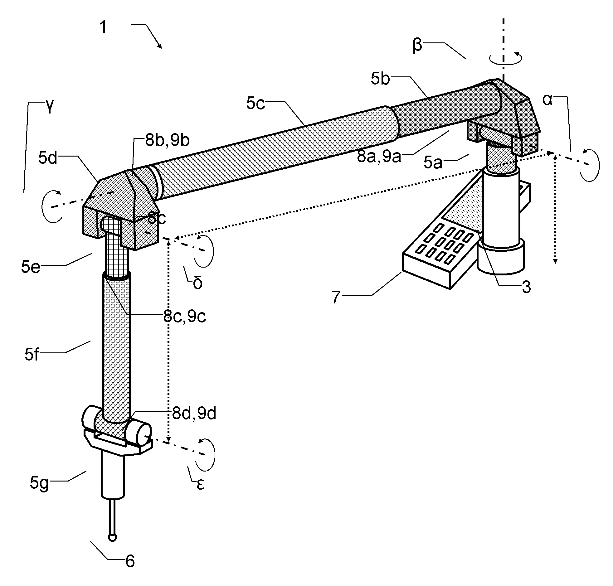
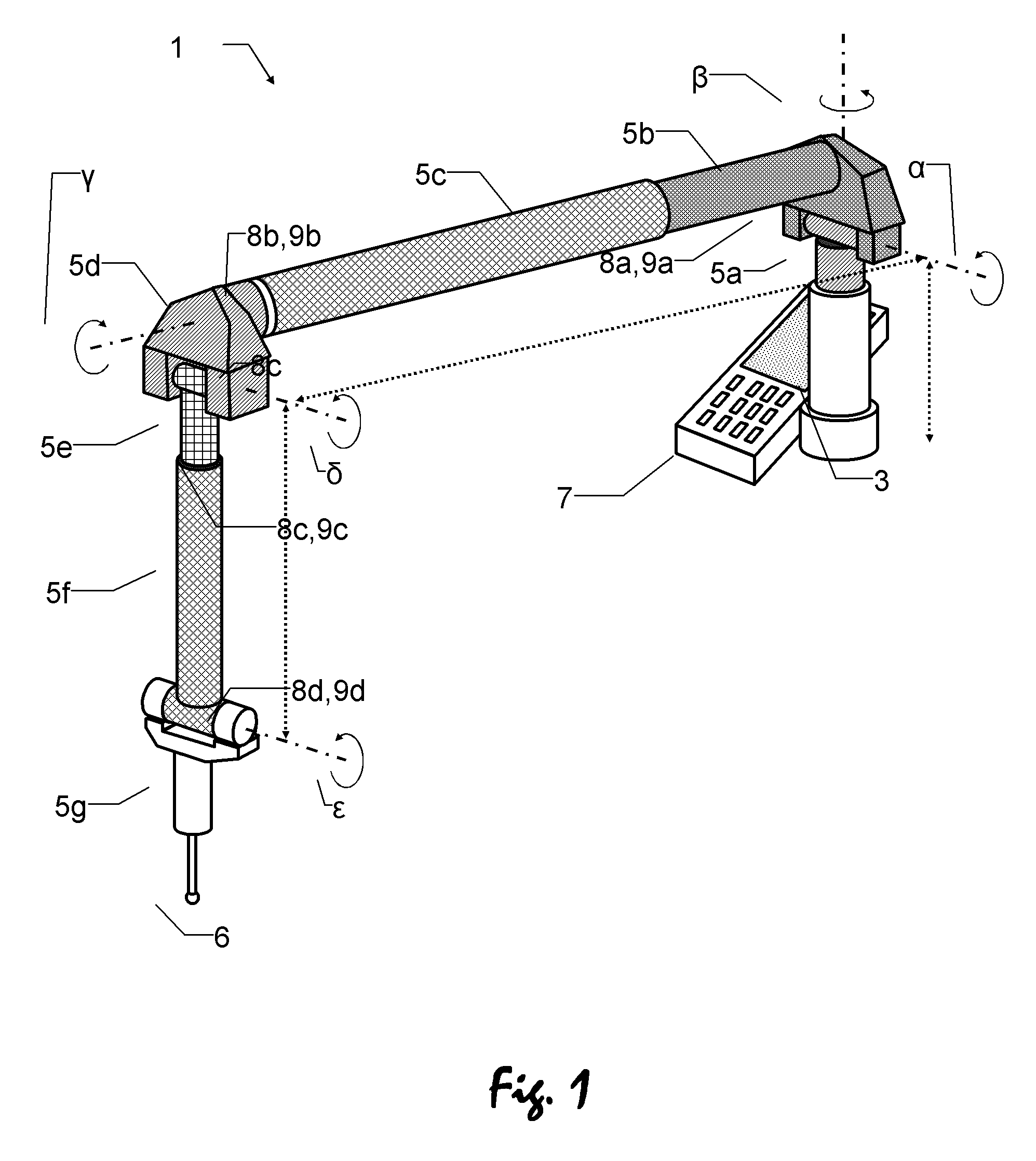
[0051]FIG. 1 shows an articulated arm CMM 1 according to the state of the art. The CMM is designed for determining a measuring position of the probe 6. Therefore, the articulated arm CMM 1 comprises a base 3 which forms the support of the CMM and which can be positioned onto a surface, particularly a floor or a table. Connected to the base 3 several arm-components 5a-5g are linked by joints 8a-8d, thus, the arm-components 5a-5g being movable relative against each other.

[0052]A first arm-component 5a is linked with and movable relative to the base 3, a second arm-component 5b is linked with and movable ...


PUM


Abstract

The invention relates to a coordinate measuring machine (CMM) for determining a measuring position of a probe. The CMM comprises an articulated arm having first and second ends and at least one joint between the first and the second end, the first end forming a base being positionable on a supporting surface, the second end being movable relative to the first end and having attached the probe. Further exists at least one sensing unit for measurement of an actual relative setting of said at least one joint and at least one computing unit for calculating a measuring position of the probe relative to the base, as well as for referencing the measuring position in an external coordinate system by using a provided base-position in the external coordinate system.

Description

BACKGROUND[0001]The present invention relates generally to a coordinate measuring machine (CMM) for determining a measuring position of a probe and a method for determining a measuring position of a probe of a coordinate measuring machine (CMM).[0002]There is a demand for high precision position measurement of object surface points in many technical fields. In particular for the manufacturing industry the measurement and quality control of produced objects have high significance.[0003]In connection with these fields there exist a number of measuring devices which are formed for such special tasks, usually being called coordinate measuring machines (CMM). One type of such devices is an articulated arm CMM, with some embodiments of such articulated arm CMMs being exemplarily described in U.S. Pat. No. 5,402,582, U.S. Pat. No. 7,051,450 and EP 1 474 650. Comparable systems are offered, for example, by the firm “ROMER” as “SIGMA”, “FLEX” or “OMEGA” and by the firm “CIMCORE” as “INFINITE...

Claims


Application Information

Patent Timeline
Patent Type & Authority Applications(United States)
IPC IPC(8): G01B5/008
CPCG01B5/008G01B7/008G05B2219/33263G05B2219/45061G05B2219/37376G05B2219/40233G05B2219/37193
Inventor PETTERSSON, BO
Owner LEICA GEOSYSTEMS AG
Why Eureka
Try Eureka