Device and method for generating electrical power

a technology of electrical power generation and electrical power, applied in the field of electrical power generation devices and systems, can solve the problems of limited battery supply power, requiring recharging, and insufficient power for an extended period of time, and achieve the effect of uniform power outpu

Active Publication Date: 2009-10-08
THE BOEING CO
View PDF16 Cites 26 Cited by
  • Summary
  • Abstract
  • Description
  • Claims
  • Application Information

AI Technical Summary

Benefits of technology

[0007]In accordance with another embodiment of the present invention, a mobile device for generating electrical power may include a combustion chamber. The device may also include a first hot plate in thermal communication with one side of the combustion chamber and a first cold plate. A first TEC module is disposed between the first hot plate and the first cold plate and in thermal communication with the first hot plate and the first cold plate to transfer thermal energy from the first hot plate to the first cold plate. A heat flux across the first TEC module causes electrical power to be generated. The device may also include a second hot plate in thermal communication with...

Problems solved by technology

Battery supplied power is limited and requires recharging.
Moreover, battery supplied power can be heavy as batteries become increasingl...

Method used


Image

  • Device and method for generating electrical power
  • Device and method for generating electrical power
  • Device and method for generating electrical power

Examples


Embodiment Construction

[0029]The following detailed description of embodiments refers to the accompanying drawings, which illustrate specific embodiments of the invention. Other embodiments having different structures and operations do not depart from the scope of the present invention.

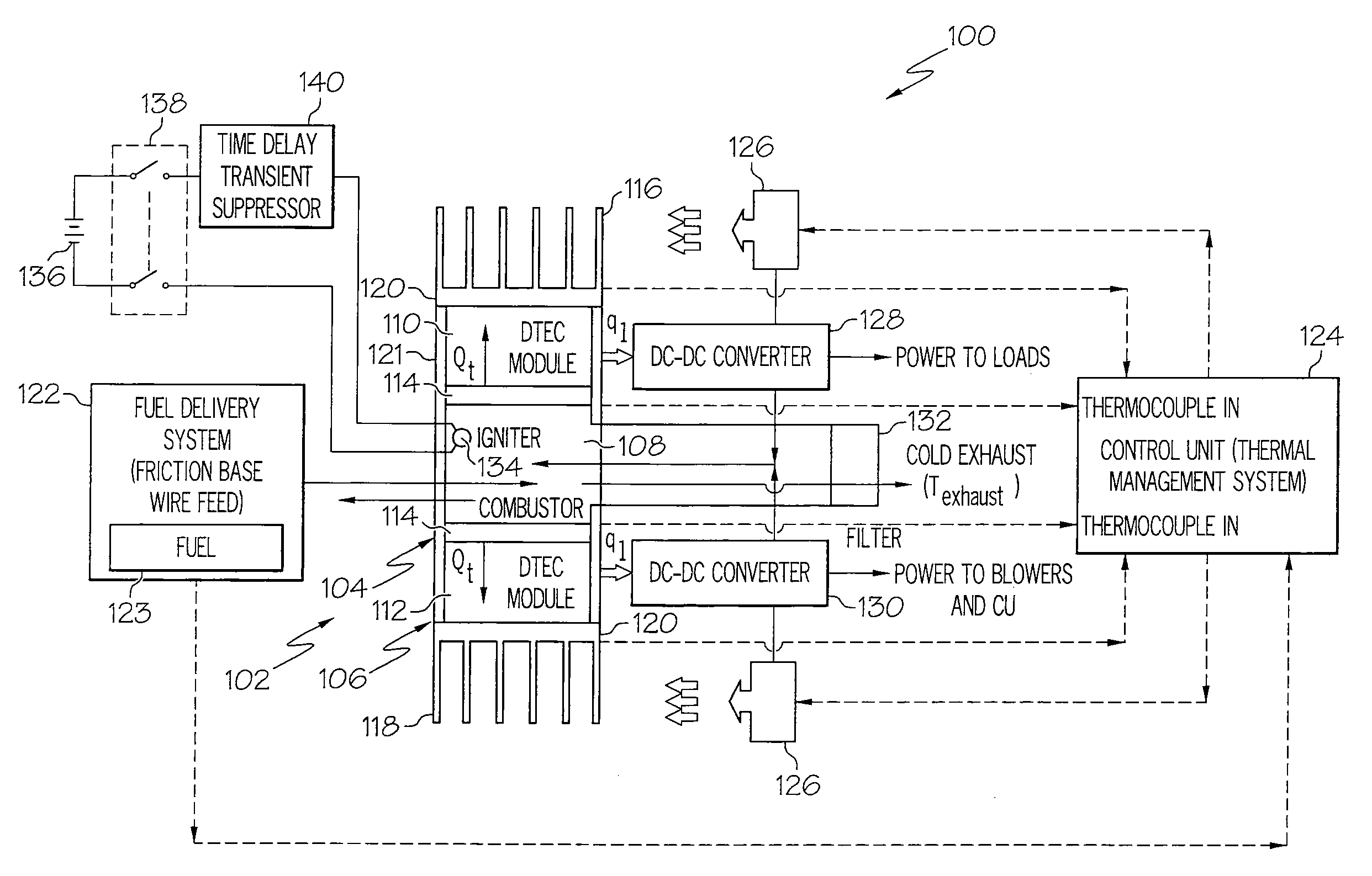
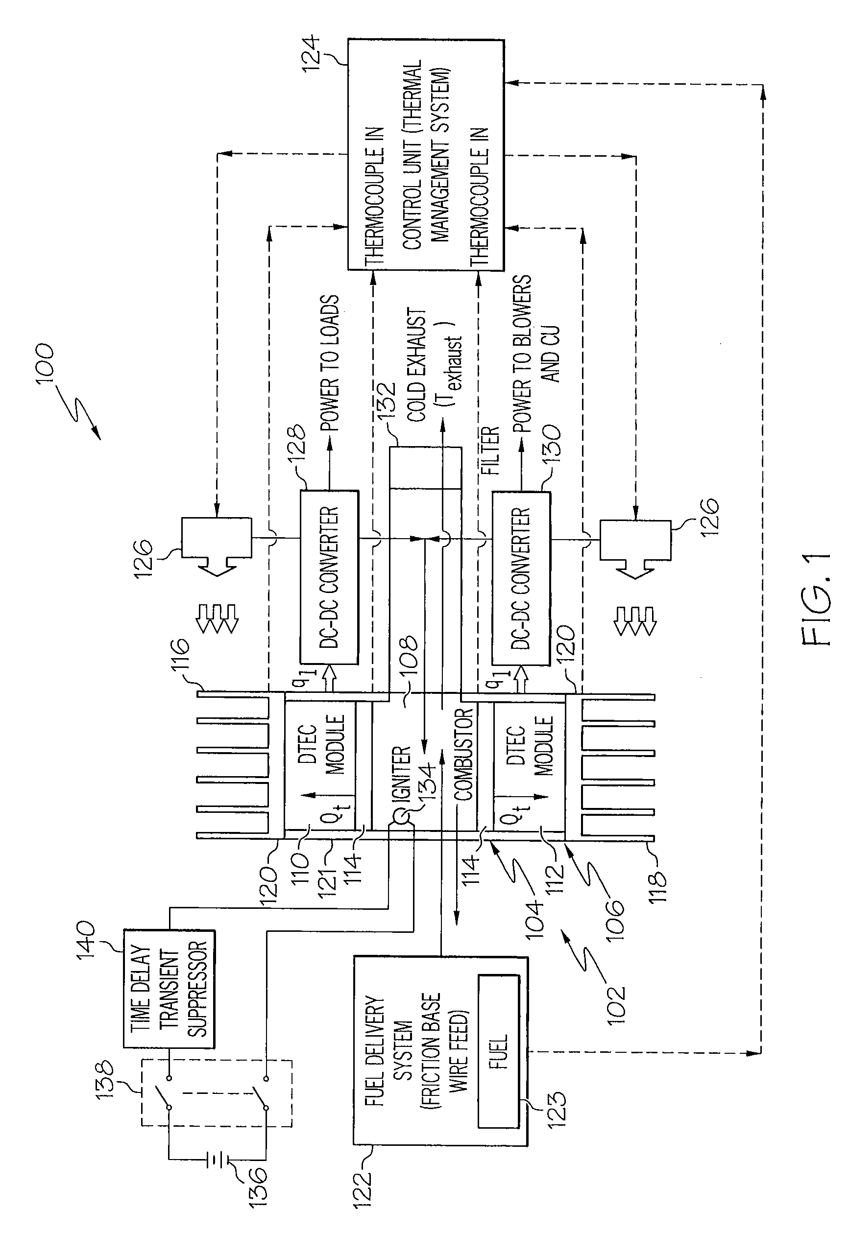
[0030]FIG. 1 is a block diagram of an example of a device 100 for generating electrical power in accordance with an embodiment of the present invention. As described herein different embodiments of the present invention may mobile and capable of being carried by personnel for powering electrical apparatus in remote areas where other power sources are unavailable. The device 100 may include a heat exchanger 102 including two concentric pipes or tubes 104 and 106. An inner pipe 104 of the two concentric pipes may form or define a combustion chamber 108. The two concentric pipes may be made from a high-heat resistant material, such as a metallic material, ceramic or other high-heat resistant material. A first thermal-to-electr...


PUM


Abstract

A mobile device for generating electrical power may include a combustion chamber and a heat sink. A TEC module is in thermal communication with the combustion chamber and the heat sink to transfer thermal energy from the combustion chamber to the heat sink. A heat flux across the TEC module causes electrical power to be generated. The mobile device may also include a fuel delivery system to feed fuel into the combustion chamber. A control system may be included to at least monitor and control delivery of fuel to the combustion chamber by the fuel delivery system and to control a temperature gradient across the TEC module to control the electrical power produced by the thermal-to-electric energy conversion device.

Description

CROSS-REFERENCE TO RELATED APPLICATIONS[0001]This application is related to application Ser. No. 11 / 937,571, filed Nov. 9, 2007, and entitled “DEVICE AND METHOD FOR GENERATING ELECTRICAL POWER.”BACKGROUND OF THE INVENTION[0002]The present invention relates to devices and systems for generating electrical power, and more particularly to a mobile device and method for generating electrical power using a thermal-to-electrical energy conversion device including and a control unit.[0003]At present, there are many ways of generating power for use in powering electronic devices. Most prevalent is the use of direct current or alternating current by means of a battery supply. Battery supplied power is limited and requires recharging. Recharging requires access to a power supply. Moreover, battery supplied power can be heavy as batteries become increasingly heavier as the power requirement increases. For example a battery having a higher power output will typically be heavier than one having ...

Claims


Application Information

Patent Timeline
IPC IPC(8): H01L35/30
CPCH01L35/32H01L35/30F28D15/0275H10N10/13H10N10/17
Inventor HUANG, JAMES PINGTSAI, CHING-FENNGUYEN, HAN V.CLEVELAND, MARK ALLENQUIAMBAO, JIMMY M.
Owner THE BOEING CO
Why Eureka
Try Eureka