Electric power steering device

a technology of electric power steering and shunt resistor, which is applied in the direction of electric controllers, instruments, ignition automatic control, etc., can solve the problems of abnormal devices, remarkable heat generation of shunt resistors, and put into power loss, so as to reduce heat generation and power loss in the device, reduce costs, and improve efficiency

Active Publication Date: 2009-10-08
MITSUBISHI ELECTRIC CORP
View PDF7 Cites 14 Cited by
  • Summary
  • Abstract
  • Description
  • Claims
  • Application Information

AI Technical Summary

Benefits of technology

[0010]The present invention has been made to solve the above problems, and therefore has an object to provide an electric power steering device which is capable of determining a failure without using a motor current, thereby providing fail safe means that is suitable for an electric power steering device with no motor current detecting means.
[0011]Another object of the present invention is to provide an electric power steering device which eliminates motor current detecting means for detecting the motor current such as a shunt resistor, and suppresses the heat generation and the power loss in the device, thereby making it possible to realize the downsized device, a reduction in costs, and the higher efficiency.

Problems solved by technology

Therefore, it is determined that the device is abnormal when a difference between the target current and the detection current becomes equal to or higher than a given value.
In recent years, the types of vehicles in which the electric power steering device is installed are expanded to a standard sized car that is large in weight, and a current of the motor is increasingly made larger, and a problem on the heat generation due to the shunt resistor becomes remarkable.
Also, a voltage drop due to the shunt resistor can be put into a power loss due to the shunt resistor, and with a larger current in recent years, the power loss due to the shunt resistor also increases, resulting in such a problem that the higher efficiency of the device is impeded.
For that reason, not only the controller gets complicated, but also a space for mounting those parts on a circuit board is required, resulting in such a problem that the controller becomes large, and the costs are increased.

Method used


Image

  • Electric power steering device
  • Electric power steering device
  • Electric power steering device

Examples


first embodiment

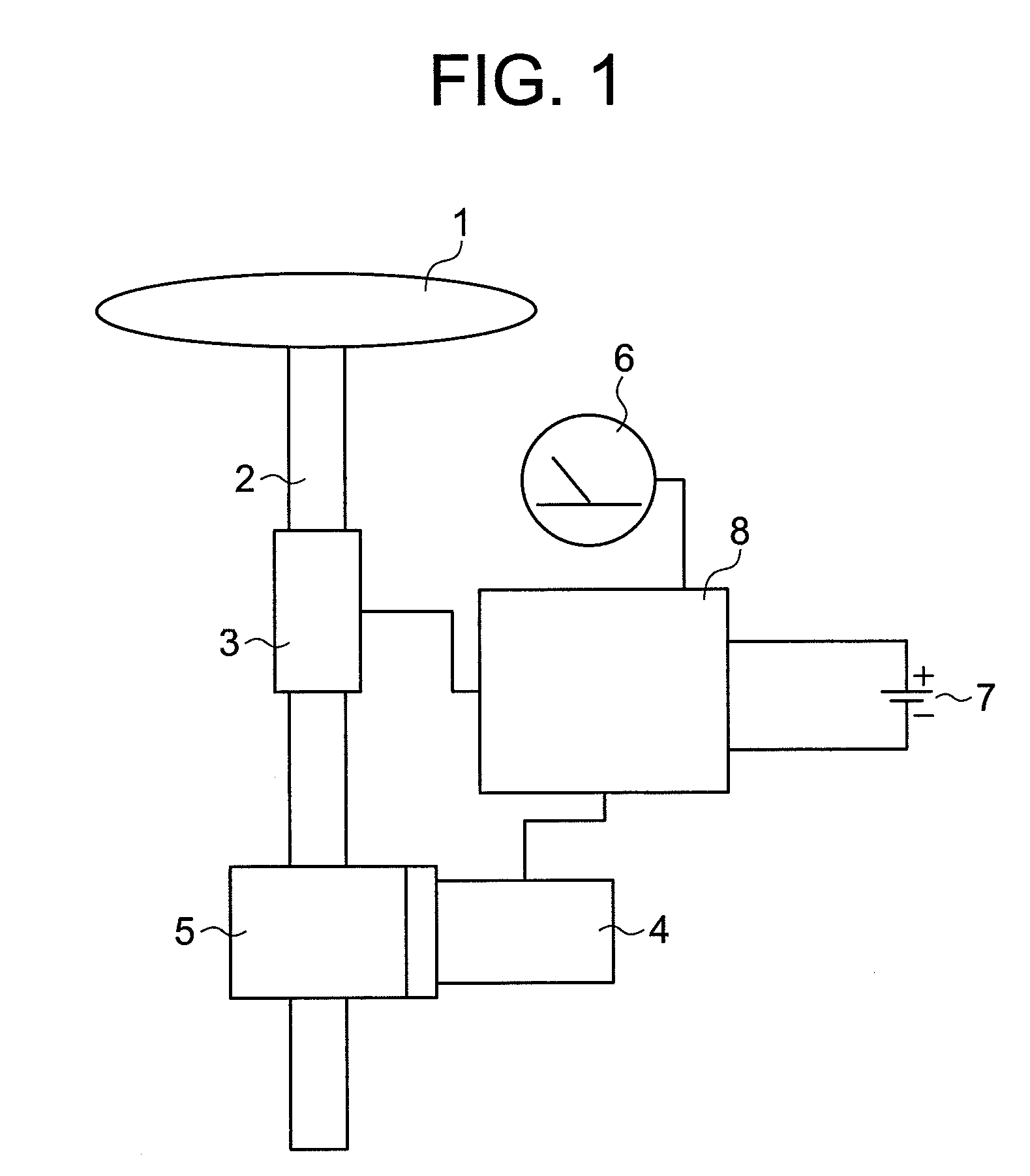
[0021]A description is given of an electric power steering device according to a first embodiment of the present invention with reference to the accompanying drawings. Referring to FIG. 1, reference numeral 1 denotes a steering wheel, reference numeral 2 denotes a steering shaft, reference numeral 3 denotes a torque sensor that detects the steering force of a driver, and reference numeral 4 denotes a motor that assists the steering force of the driver. In FIG. 1, reference numeral 5 denotes a speed reducer for transmitting the output torque of the motor to the steering shaft 2, reference numeral 6 denotes a vehicle speed sensor that detects the travel velocity of a vehicle, reference numeral 7 denotes a power supply (battery) that is mounted in the vehicle, and reference numeral 8 denotes a controller that drives the motor 4 based on the output signals of the torque sensor 3 and the vehicle speed sensor 6.

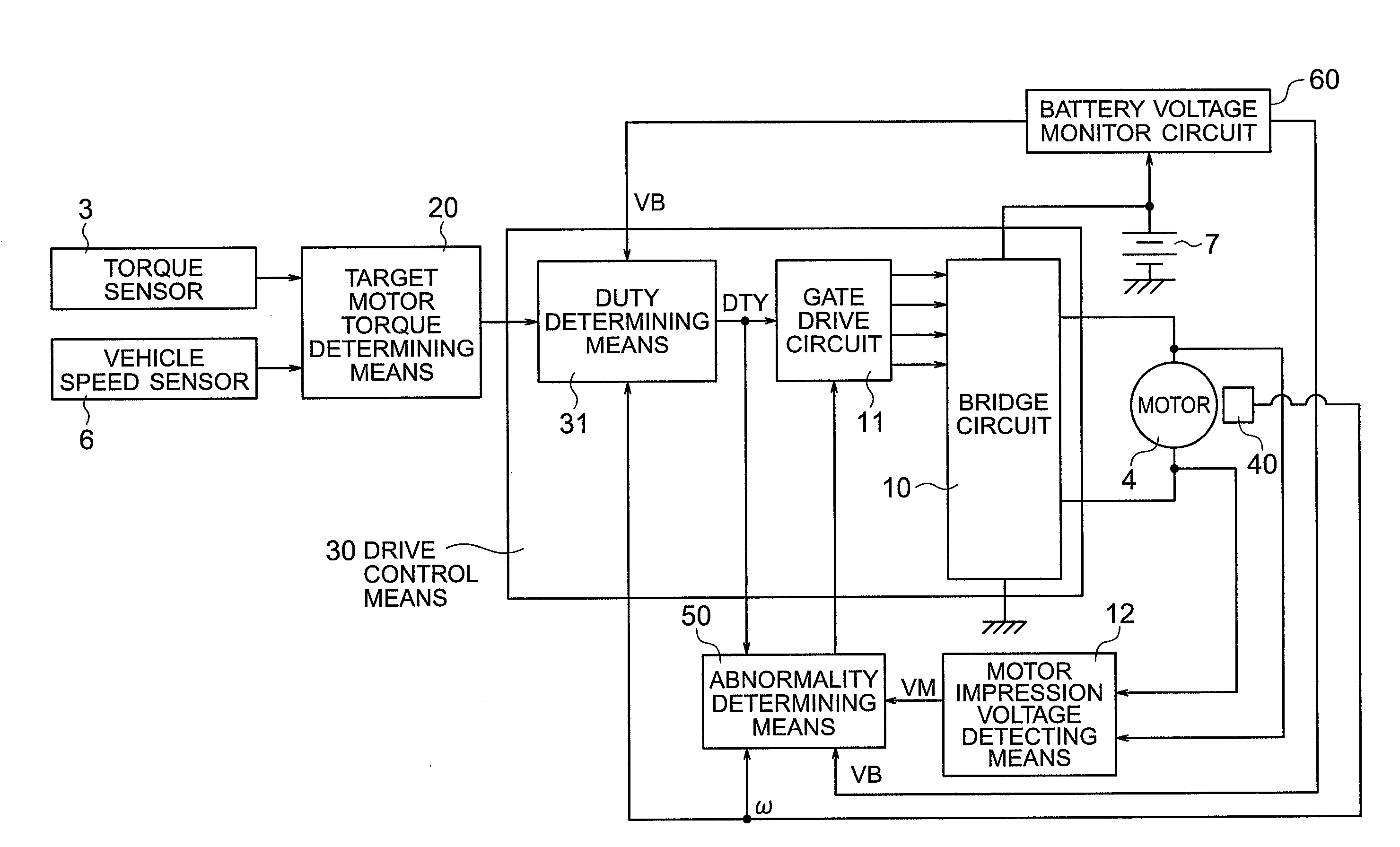
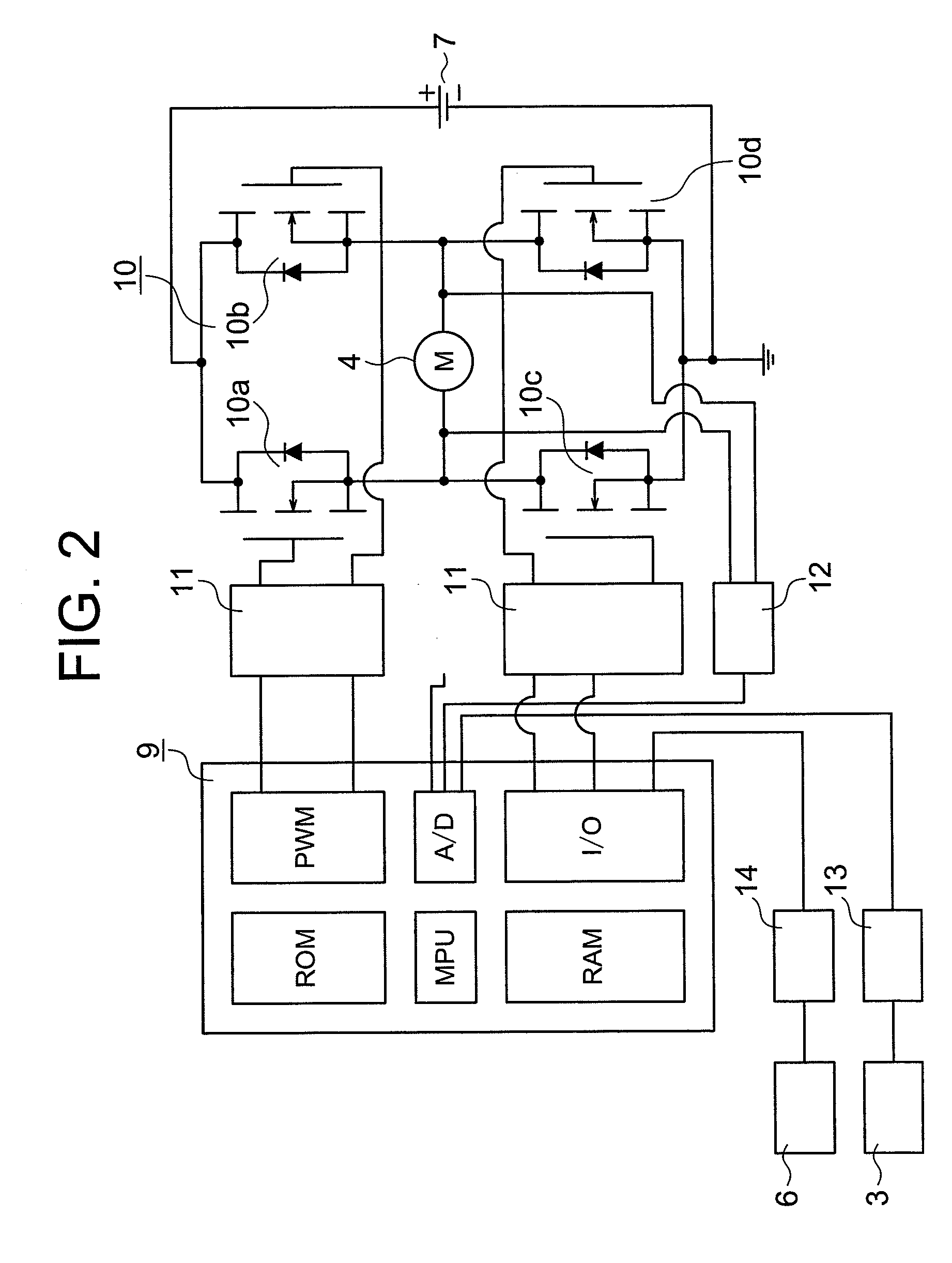
[0022]FIG. 2 is a diagram showing the details of the controller 8. Reference n...


PUM


Abstract

Provided are an electric power steering device which is capable of determining a failure without using a motor current, and an electric power steering device which removes any motor current detecting unit for detecting the motor current such as a shunt resistor, and suppresses the heat generation and the power loss in the device, thereby making it possible to realize the downsized device, a reduction in the costs, and the higher efficiency. An electric power steering device according to the present invention includes: a motor coupled with a steering system; a drive control unit for controlling a drive of the motor; a motor impression voltage detecting unit for detecting an applied voltage of the motor; and an abnormality determining unit for determining abnormality based on a comparison result of the detected motor impression voltage and an output voltage of the drive control unit.

Description

BACKGROUND OF THE INVENTION[0001]1. Field of the Invention[0002]The present invention relates to an electric power steering device that generates a steering assist torque with a motor.[0003]2. Description of the Related Art[0004]Up to now, there has been proposed a control method in which a torque sensor that detects a steering torque of a steering system and a vehicle speed sensor that detects a vehicle speed are disposed, and the assist torque of a motor is controlled based on the outputs of those sensors, and the inertia and viscosity of a steering system are compensated based on the angular velocity and the angular acceleration of the motor in addition to the above outputs in order to improve the steering feeling in an electric power steering device.[0005]In the conventional electric power steering device, as described above, a target current is determined according to a target motor torque which is determined based on the steering torque, and the angular velocity and angular ac...

Claims


Application Information

Patent Timeline
Patent Type & Authority Applications(United States)
IPC IPC(8): B62D5/04
CPCB62D5/0487
Inventor KIFUKU, TAKAYUKI
Owner MITSUBISHI ELECTRIC CORP
Why Eureka
Try Eureka