Component separating device and method of separating component
a technology of component separation and component, which is applied in the direction of separation process, instruments, laboratory glassware, etc., can solve the problems of difficult to accurately position the duct and the ultrasonic transducer, not so much suitable for separation, and difficult to design the ultrasonic transducer in a free and free way. , to achieve the effect of high separation accuracy, reduced vibration loss and small siz
- Summary
- Abstract
- Description
- Claims
- Application Information
AI Technical Summary
Benefits of technology
Problems solved by technology
Method used
Image
Examples
first exemplary embodiment
[0068]An explanation will be given of a component separating device and a method of separating a component using the device according to Embodiment 1 of the invention in reference to the drawings as follows.
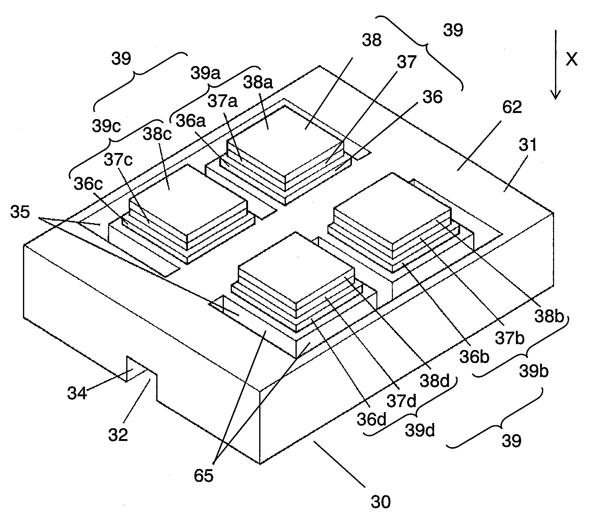
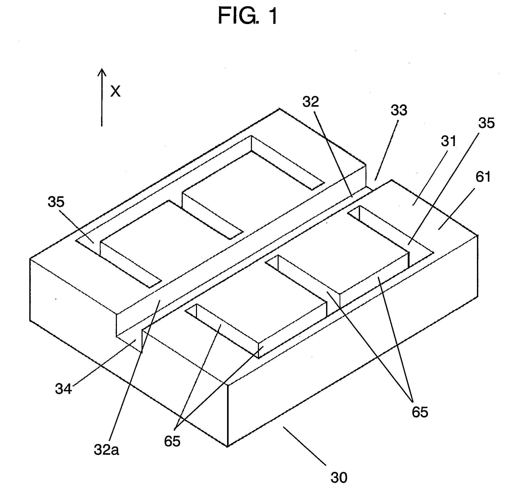
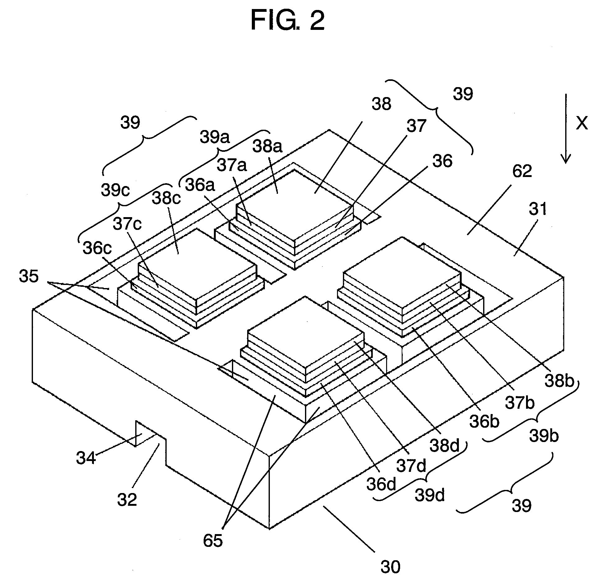
[0069]FIG. 1 is a perspective view showing a constitution of a component separating device according to Embodiment 1 of the invention. FIG. 2 is a perspective view of the component separating device shown in FIG. 1 viewed from a lower face side thereof. FIG. 3 is a plane view of the component separating device shown in FIG. 1. FIG. 4 is a sectional view taken along a line 4-4 of the component separating device shown in FIG. 3.
[0070]FIG. 5 through FIG. 8 are schematic views for explaining a method of separating a component using the component separating device shown in FIG. 1. FIG. 9 through FIG. 14 are sectional views for explaining a method of fabricating the component separating device shown in FIG. 1.
[0071]In FIG. 1 through FIG. 4, substrate 31 is formed by constituting a mate...
second exemplary embodiment
[0122]An explanation will be given of a component separating device according to Embodiment 2 of the invention in reference to the drawings as follows.
[0123]FIG. 16 is a sectional view showing a configuration of the component separating device according to Embodiment 2 of the invention. A point by which Embodiment 2 differs from Embodiment 1 resides in a sectional shape of a groove. Groove 35b according to Embodiment 2 includes first opening portion 52b (hereinafter, referred to as opening portion 52b) on the side of lower face 62 and second opening portion 53b (hereinafter, referred to as opening portion 53b) on the side of upper face 61. Further, opening portion 52b is smaller than opening portion 53b. Thereby, an angle made by wall face 65b, which is a wall face provided at a side of the fluid channel of groove 35b, and lower face 62 provided with actuators 39 is an acute angle.
[0124]The vibration generated by actuator 39 includes a vibration component directly transmitted to flu...
third exemplary embodiment
[0127]An explanation will be given of a component separating device according to Embodiment 3 of the invention in reference to the drawings as follows.
[0128]FIG. 17 is a sectional view showing a configuration of the component separating device according to Embodiment 3 of the invention. A point by which Embodiment 3 differs from Embodiments 1 or 2 resides in a sectional shape of a groove. A groove 35c according to Embodiment 3 includes first opening portion 52c (hereinafter, referred to as opening portion 52c) on the side of lower face 62 and second opening portion 53c (hereinafter, referred to as opening portion 53c) on the side of upper face 61. Opening portion 52c and opening portion 53c are connected by wall face 65c. A sectional shape of wall face 65c is constituted by a circular arc or an elliptical curve having a center at a side of groove 35c.
[0129]By such a constitution, the vibration generated by actuators 39 is reflected by wall face 65c and the distance of reaching flui...
PUM
| Property | Measurement | Unit |
|---|---|---|
| angle | aaaaa | aaaaa |
| acute angle | aaaaa | aaaaa |
| frequency | aaaaa | aaaaa |
Abstract
Description
Claims
Application Information
 - R&D
- Intellectual Property
- Life Sciences
- Materials
- Tech Scout
- Unparalleled Data Quality
- Higher Quality Content
- 60% Fewer Hallucinations
Browse by: Latest US Patents, China's latest patents, Technical Efficacy Thesaurus, Application Domain, Technology Topic, Popular Technical Reports.
© 2025 PatSnap. All rights reserved.Legal|Privacy policy|Modern Slavery Act Transparency Statement|Sitemap|About US| Contact US: help@patsnap.com


