Component separating device and method of separating component

a technology of component separation and separating device, which is applied in the direction of separation process, liquid displacement, laboratory glassware, etc., can solve the problems of difficult to accurately position the duct and the ultrasonic transducer, not so much suitable for separation, and inability to design the ultrasonic transducer in a free and free way, etc., to achieve high separation accuracy, reduce vibration loss, and small size

Inactive Publication Date: 2011-06-28
PANASONIC CORP
View PDF7 Cites 70 Cited by
  • Summary
  • Abstract
  • Description
  • Claims
  • Application Information

AI Technical Summary

Benefits of technology

[0012]The invention provides a component separating device and a method of separating a component capable of separating respective components highly accurately even by a small amount of a sample by generating an acoustic standing wave having a strong intensity.
[0013]A component separating device of the invention includes a substrate, a fluid channel provided at the substrate, an actuator and a groove provided at a surrounding of the actuator. The fluid channel contains a fluid including a liquid component and a solid component, and the actuator generates a standing wave at inside of the fluid channel. By this constitution, a vibration loss is reduced by reflecting a vibration by the groove to be transmitted to a side of the fluid channel, the standing wave having a strong intensity is generated at inside of the fluid channel to provide a small-sized and highly accurate component separating device.
[0014]A method of separating a component of the invention includes a fluid containing step, a standing wave generating step, a reflecting step and a separating step. At the fluid containing step, a fluid including a liquid component and a solid component is contained in a fluid channel provided at a substrate. At the standing wave generating step, a standing wave, which has a node at an inner portion of the fluid channel, is generated by generating a vibration by applying a high frequency voltage to a plurality of actuators provided to be opposed to the fluid channel to thereby. At the reflecting step, the vibration reflects at a groove provided at a surrounding of the actuator, the groove is provided at the surrounding excluding a side of the fluid channel, and at the separating step, at least either one of the liquid component and the solid component is separated from the fluid. By this constitution, a vibration loss is reduced by reflecting the vibration by the groove to be transmitted to the side of fluid channel, the standing wave having a strong intensity is generated at inside of the fluid channel to thereby provide the highly accurate method of separating the components.

Problems solved by technology

In separating the components by the centrifugal separator, in view of operation of the centrifugal separator, a constant amount or more of a fluid is needed and the separation is not suitable so much when a sample amount is small.
Thereby, there is not a freedom of designing the ultrasonic transducer, further, it is difficult to accurately position the duct and the ultrasonic transducer.

Method used


Image

  • Component separating device and method of separating component
  • Component separating device and method of separating component
  • Component separating device and method of separating component

Examples


first exemplary embodiment

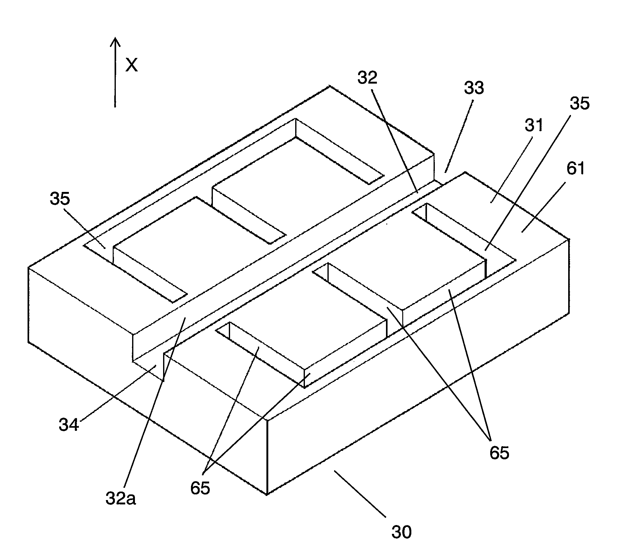
[0068]An explanation will be given of a component separating device and a method of separating a component using the device according to Embodiment 1 of the invention in reference to the drawings as follows.

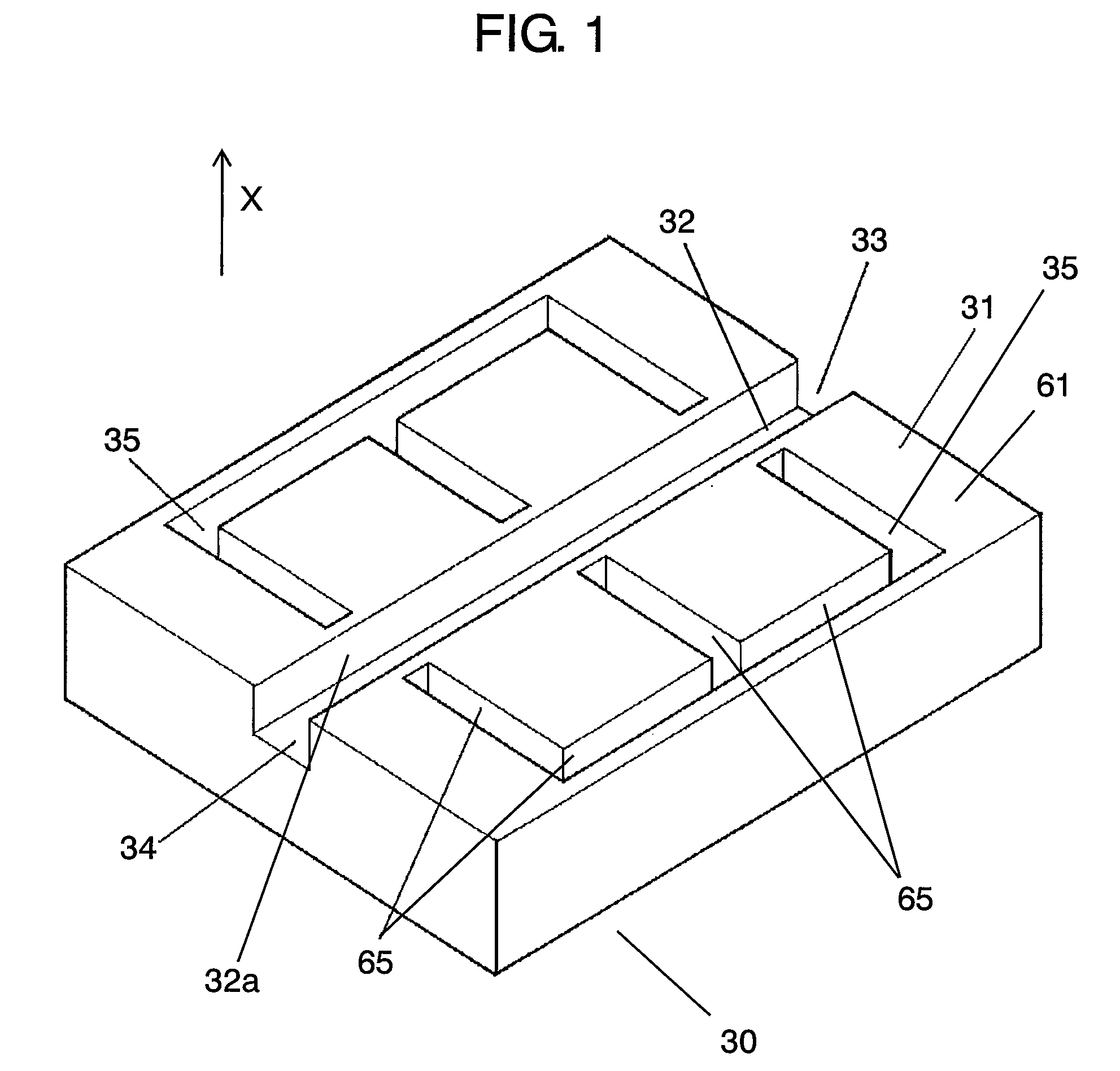
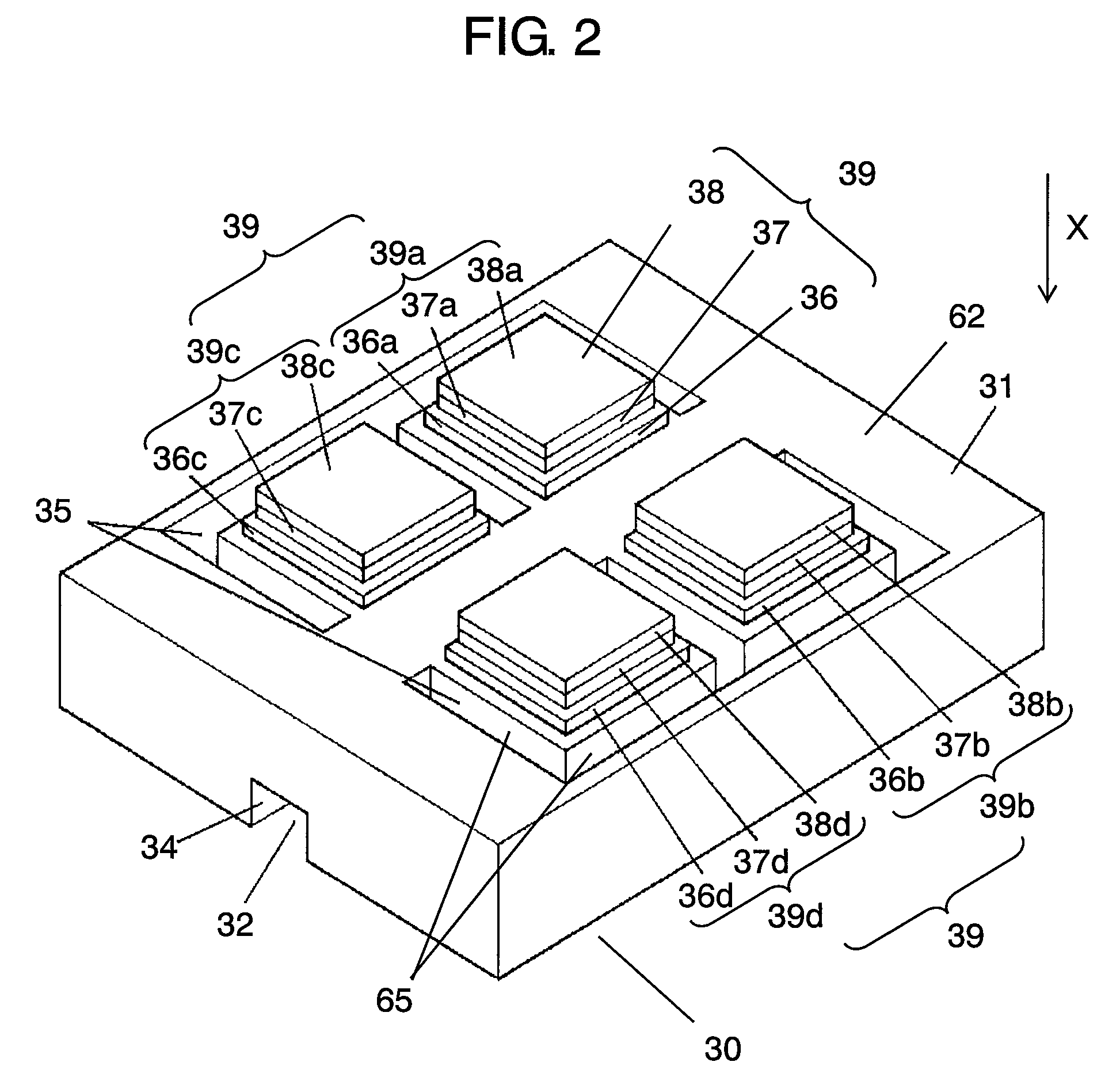
[0069]FIG. 1 is a perspective view showing a constitution of a component separating device according to Embodiment 1 of the invention. FIG. 2 is a perspective view of the component separating device shown in FIG. 1 viewed from a lower face side thereof. FIG. 3 is a plane view of the component separating device shown in FIG. 1. FIG. 4 is a sectional view taken along a line 4-4 of the component separating device shown in FIG. 3.

[0070]FIG. 5 through FIG. 8 are schematic views for explaining a method of separating a component using the component separating device shown in FIG. 1. FIG. 9 through FIG. 14 are sectional views for explaining a method of fabricating the component separating device shown in FIG. 1.

[0071]In FIG. 1 through FIG. 4, substrate 31 is formed by constituting a mate...

second exemplary embodiment

[0122]An explanation will be given of a component separating device according to Embodiment 2 of the invention in reference to the drawings as follows.

[0123]FIG. 16 is a sectional view showing a configuration of the component separating device according to Embodiment 2 of the invention. A point by which Embodiment 2 differs from Embodiment 1 resides in a sectional shape of a groove. Groove 35b according to Embodiment 2 includes first opening portion 52b (hereinafter, referred to as opening portion 52b) on the side of lower face 62 and second opening portion 53b (hereinafter, referred to as opening portion 53b) on the side of upper face 61. Further, opening portion 52b is smaller than opening portion 53b. Thereby, an angle made by wall face 65b, which is a wall face provided at a side of the fluid channel of groove 35b, and lower face 62 provided with actuators 39 is an acute angle.

[0124]The vibration generated by actuator 39 includes a vibration component directly transmitted to flu...

third exemplary embodiment

[0127]An explanation will be given of a component separating device according to Embodiment 3 of the invention in reference to the drawings as follows.

[0128]FIG. 17 is a sectional view showing a configuration of the component separating device according to Embodiment 3 of the invention. A point by which Embodiment 3 differs from Embodiments 1 or 2 resides in a sectional shape of a groove. A groove 35c according to Embodiment 3 includes first opening portion 52c (hereinafter, referred to as opening portion 52c) on the side of lower face 62 and second opening portion 53c (hereinafter, referred to as opening portion 53c) on the side of upper face 61. Opening portion 52c and opening portion 53c are connected by wall face 65c. A sectional shape of wall face 65c is constituted by a circular arc or an elliptical curve having a center at a side of groove 35c.

[0129]By such a constitution, the vibration generated by actuators 39 is reflected by wall face 65c and the distance of reaching flui...


PUM

PropertyMeasurementUnit
angleaaaaaaaaaa
acute angleaaaaaaaaaa
frequencyaaaaaaaaaa

Abstract

A component separating device includes a substrate, a fluid channel provided at the substrate, an actuator and a groove provided at a surrounding of the actuator, the fluid channel contains a fluid including a liquid component and a solid component, and the actuator generates a standing wave at inside of the fluid channel. By such a constitution, a vibration loss is reduced by reflecting a vibration by the groove to be transmitted to a side of the fluid channel, the standing wave having a strong intensity is generated at inside of the fluid channel, and the small-sized highly accurate component separating device is provided.

Description

[0001]This Application is a U.S. National Phase Application of PCT International Patent Application No. PCT / JP2006 / 308542, filed Apr. 24, 2006.TECHNICAL FIELD[0002]The present invention relates to a component separating device and a method of separating a component for separating a fluid mixed with a liquid component and a solid component, represented by blood, milky liquid or the like into respective components.BACKGROUND ART[0003]As a fluid mixed with a solid component and a liquid component, for example, river water, sea water, blood, milky liquid or the like is included. Solid components of sand, bacteria, blood cell, emulsion or the like included in the fluids are present at inside of the fluids in a state of precipitation, dispersion or the like. That is, the solid component is present as a solid without being dissolved in the liquid component.[0004]An explanation will be given of a method, a device of separating the fluid mixed with the solid component and the liquid componen...

Claims


Application Information

Patent Timeline
Patent Type & Authority Patents(United States)
IPC IPC(8): B01D43/00B01J19/00C02F1/36
CPCB01D21/283B01D43/00B01L3/502753B01L3/502761B01L3/502769B01J2219/00783B01J2219/00905G01N2001/4094B01L2200/0647B01L2300/0816B01L2300/0864B01L2400/0439C02F1/36G01N1/40
Inventor TAKAHASHI, MAKOTONAKATANI, MASAYA
Owner PANASONIC CORP
Why Eureka
Try Eureka