Electric motor

Inactive Publication Date: 2009-10-08
KONE CORP
View PDF13 Cites 35 Cited by
  • Summary
  • Abstract
  • Description
  • Claims
  • Application Information

AI Technical Summary

Benefits of technology

[0041]The solution of the invention provides the advantage that the torque ripple of the motor can be substantially reduced when the width of the slot opening is at least 75% of the width of the slot bottom. The fundamental torque wave still remains substantially unchanged. This is advantageous when a conveying apparatus is driven by a drive motor according to the invention, because torque ripple is a disadvantage in the operation of the conveying apparatus, such as an elevator, and impairs its traveling comfort, causing vibration and noise. The vibration appears as vibration at the characteristic frequency of the elevator mechanism, and as constrained oscillation, which makes the system oscillate even if the frequency of the excitation is not the same as the characteristic frequency of the elevator mechanism. Vibration also causes wear of the mechanism of the conveying apparatus and reduces its useful life.
[0042]When the width of the slot opening is at least 75% of the width of the slot bottom, the slot opening can be regarded as being substantially open. This also facilitates the winding of the motor. The windings can be prepared as finished coils before being fitted in place, because, the slot opening being substantially open, the windings can be fitted in place on a finished rotor and/or stator. Further, according to the manufacturing method described in the invention, a motor phase winding can be wound as a coil from a single continuous conductor e.g. mechanically by using a winding coiler, which facilitates the winding operation and reduces the manufacturing costs of the motor.
[0043]By virtue of the c

Problems solved by technology

Moreover, the magnitude of the torque fluctuates (torque ripple) and additional losses occur in the motor.
A significant proportion of the conductor material used in the motor windings is not exploited, because the end windings generate no torque but cause losses and require space.
Further, because in this construction the end windings of different phases cross with each other, the risk of short-circuit between coils is increased.
A motor provided with traditional distributed windings is also bulky and heavy due to the long end windings and the fact that the coils of a winding are usually distributed in many slots in the area of a pole pair.
This is a disadvantage especially in motors used in elevators, because elevators are increasingly being implemented using machine solutions in which the machine is placed between a guide rail and a wall of the elevator shaft.
Therefore, a large si

Method used


Image

  • Electric motor
  • Electric motor
  • Electric motor

Examples


Embodiment Construction

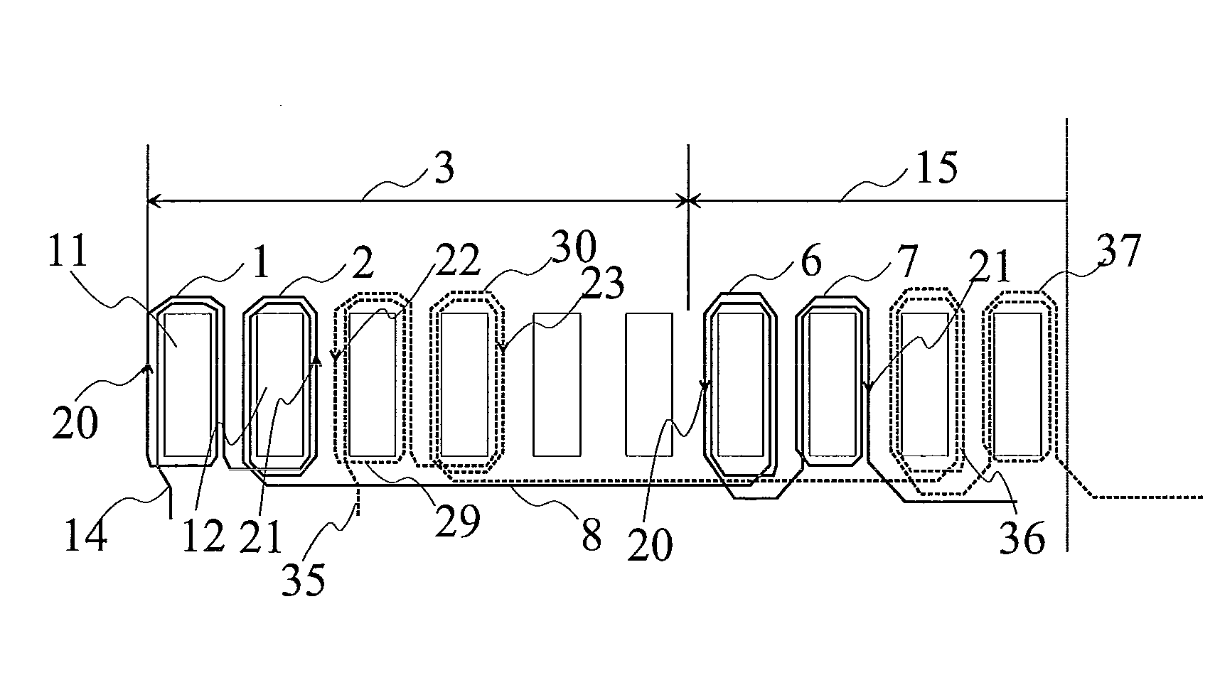
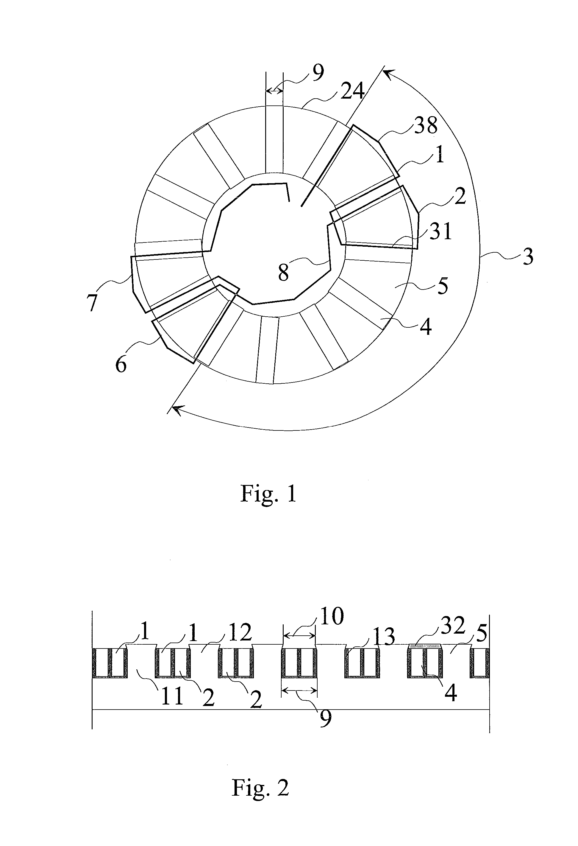
[0051]In the examples to be described in the following, the invention is set forth by the aid of a three-phase motor in which the stator is provided with a concentrated fractional-slot winding and the rotor with permanent magnets. In this embodiment of the invention, the coils comprised in the phase winding are wound in series, but they can also be wound in parallel.

[0052]FIG. 1 represents an axial-flux machine stator provided with a concentrated fractional-slot winding. The stator comprises slots 4 and teeth 5. The coils are wound around teeth to form a concentrated winding in a manner such that the coil sides 31 of the same coil are placed in mutually adjacent slots. In this way, the end windings 38 remain short as they only extend between two adjacent slots. Coils 1 and 2 form a first coil pair of the first phase, and coils 6 and 7 form a second coil pair of the first phase. The figure shows the distance 3 between the first and the second coil pairs. This distance is also the ext...


PUM

PropertyMeasurementUnit
Fractionaaaaaaaaaa
Fractionaaaaaaaaaa
Currentaaaaaaaaaa

Abstract

The present invention relates to an electric motor and to a method for manufacturing an electric motor. The electric motor comprises at least a stator (24), a rotor (25) and an air gap (26) between these, in which motor the stator and/or rotor comprises slots (4) and teeth (5) between slots, and in which the stator and/or rotor has a concentrated winding fitted in the slots. In the method of the invention, the phase windings are fitted as a concentrated fractional-slot winding.

Description

FIELD OF THE INVENTION[0001]The present invention relates to an electric motor as defined in claim 1 and to a method for manufacturing an electric motor as defined in claim 8.BACKGROUND OF THE INVENTION[0002]Electric motors are used to convert electric energy into mechanical energy. In electric motors of normal construction, it is possible to distinguish certain basic components, such as a rotor fitted to be rotatable, a rotor axle, a stationary stator, bearings and end shields. The rotor is supported by the bearings. Generally a small air gap is left between rotor and stator.[0003]The operation of rotating multi-phase alternating current machines, such as multi-phase synchronous and asynchronous motors, is based on a magnetic field rotating within the machine. A multi-phase stator winding is formed in such a way that, when a sinusoidal voltage is fed into the phase windings—the voltages fed into the phases having a phase shift of 360 / n degrees between them, where n is the number of...

Claims


Application Information

Patent Timeline
IPC IPC(8): H02K3/28H02K15/06H02K1/27
CPCH02K1/146H02K1/165Y10T29/49009H02K29/03H02K21/24H02K3/28H02K3/04
Inventor HUPPUNEN, JUSSITENHUNEN, ASMOALKULA, PETRIOLKKONEN, MIKA
Owner KONE CORP
Why Eureka
Try Eureka