Attraction and repulsion of magnetic of magnetizable objects to and from a sensor surface
a magnetizable object and magnetizable technology, applied in the direction of relays, magnetic variables, instruments, etc., can solve the problems of large energy dissipation, difficult to do population analysis, and inability to detail spatial control of the field, and achieve good magnetic sensor devices. , the effect of good magnetization method
- Summary
- Abstract
- Description
- Claims
- Application Information
AI Technical Summary
Benefits of technology
Problems solved by technology
Method used
Image

Examples
first embodiment
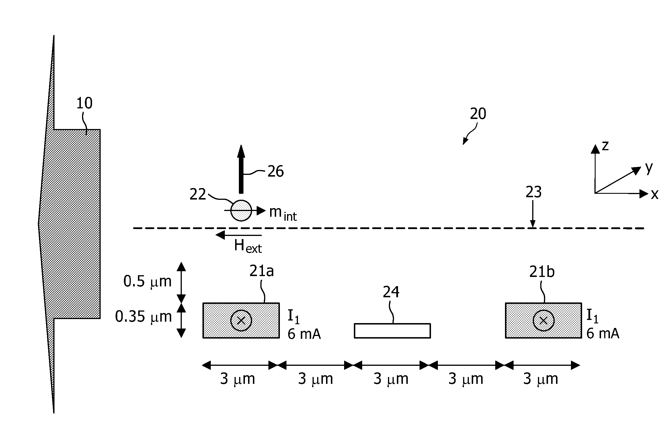
[0092]According to the invention, a magnetic sensor device 20 is provided which comprises a second magnetic field generating means formed by an external magnetic field generating means. The external magnetic field generating means may be used to put the binding of magnetic particles 22 to a sensor surface 23 under stringency.
[0093]FIG. 8 illustrates a magnetic sensor device 20 which uses an external magnet, in combination with an integrated magnetic field generating means 21a, 21b, for repelling the magnetic particles 22 from the sensor surface 23. Therefore, the magnetic sensor device 20 according to the first embodiment comprises a first magnetic field generating means 21a, 21b for generating a first magnetic field for attracting magnetic particles 22 to the sensor surface 23. The first magnetic field generating means 21a, 21b is integrated in the sensor device 20. According to the example given in FIG. 8, the first integrated magnetic field generating means 21a, 21b may comprise ...
second embodiment
[0101]The second magnetic field generating means may, be formed by an external magnetic field generating means (not shown in the drawings). The second magnetic field generating means generates a second magnetic field Hext in a second direction and having a second magnetic field strength.
[0102]According to embodiments of the invention, the magnetic sensor device 20 according to the second embodiment of the invention, may furthermore comprise a third magnetic field generating means 28, for example formed by two current wires 28a, 28b, for generating a third magnetic field for orienting dipolar magnetic fields generated by the magnetic moment of the magnetic particles 22 as explained hereinafter. A current flowing through the third magnetic field generating means 28 generates a third magnetic field which magnetizes the magnetic particles 22 present at the sensor surface 23. The magnetic particles 22 hereby develop a magnetic moment m. The magnetic moment m then generates dipolar magne...
third embodiment
[0112]A magnetic sensor device 20 according to the invention is illustrated in FIG. 15. The magnetic sensor device 20 comprises a first magnetic field generating means 21a, 21b which may be used for generating a first magnetic field for attracting magnetic particles 22 to the sensor surface 23. The first magnetic field generating means 21a, 21b is integrated in the sensor device 20. According to the example given in FIG. 15, the first integrated magnetic field generating means 21 may comprise a first and second current wire 21a, 21b respectively. This example is not limiting the invention, the first integrated magnetic field generating means 21 may also comprise only one current wire or may comprise more than two current wires. The invention will further be described by means of the first integrated magnetic field generating means comprising first and second current wires 21a, 21b but this is not intended to limit the invention.
[0113]By sending a first current through at least one o...
PUM
 Abstract
Description
Claims
Application Information
PatSnap Eureka turns technology decisions into work you can execute. Powered by our Innovation Knowledge Graph, it runs expert workflows across engineering, life sciences, materials and intellectual property. Get your review-ready output in minutes.


