Light-emitting display device appling crystal

a technology of light-emitting display and crystal, which is applied in the field of light-emitting display devices equipped with transparent crystals, can solve the problems of significantly reducing the efficiency of the entire module, and the output of the solace cell plate, and achieves the effect of clearly displaying the display information, maximizing the power generation of the solar cell module, and maximizing the light emission

Inactive Publication Date: 2009-10-08
HAE SUNG SOLAR +1
View PDF3 Cites 9 Cited by
  • Summary
  • Abstract
  • Description
  • Claims
  • Application Information

AI Technical Summary

Benefits of technology

[0013]In the present invention, a sunshine is effectively concentrated using a reflection surface of an inner vertical side of a transparent crystal, and a power generation of a solar cell module is maximized, and in a nighttime, the light emission is maximized using a crystal, and the light emitted from a light emitting device is reflected by a reflection surface of a vertical side surface of the crystal, so that it is possible to more clearly display a display information such as a character or image etched on a crystal.

Problems solved by technology

However, when a certain shadow is formed at a certain portion of the solar cell module, the shadow portion may disturb the generation of the current since it becomes a nonconductive portion (resistance), the output of the solace cell plate significantly decreases, and the entire efficiency of the module also significantly decreases.
Since the light from the display device is nearly reflected in a vertical direction, it is impossible to recognize the contents displayed by the display device in all directions, so that an inherent function is not performed.

Method used


Image

  • Light-emitting display device appling crystal
  • Light-emitting display device appling crystal
  • Light-emitting display device appling crystal

Examples


Embodiment Construction

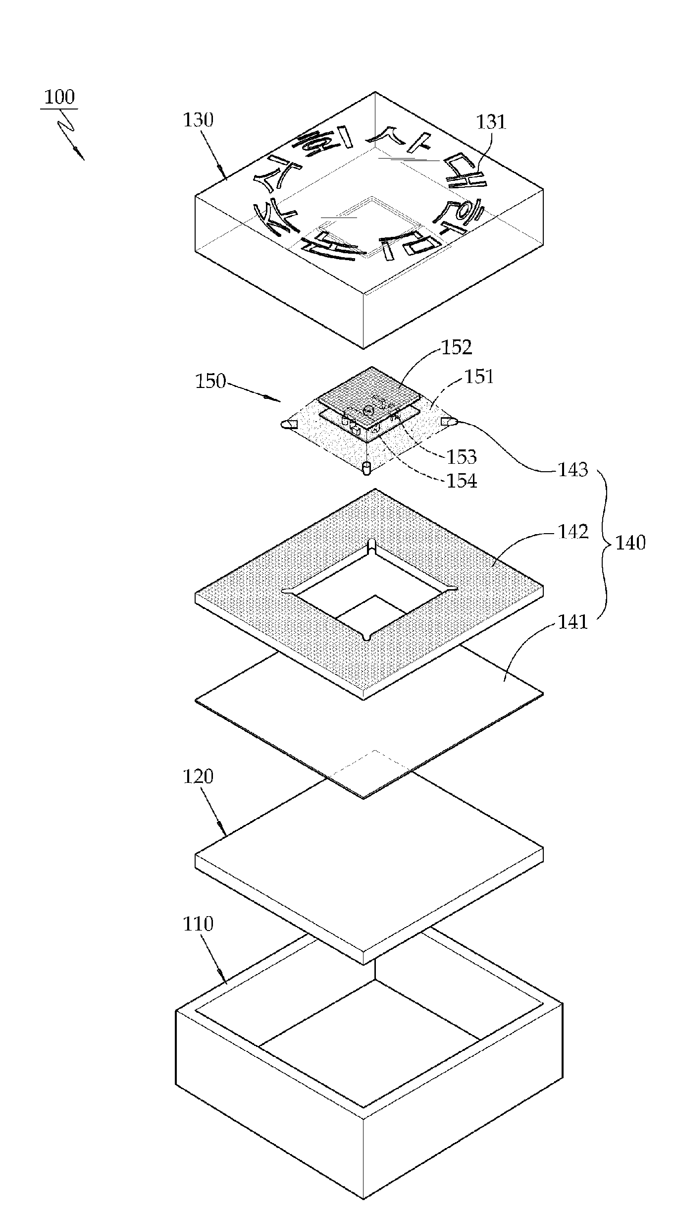
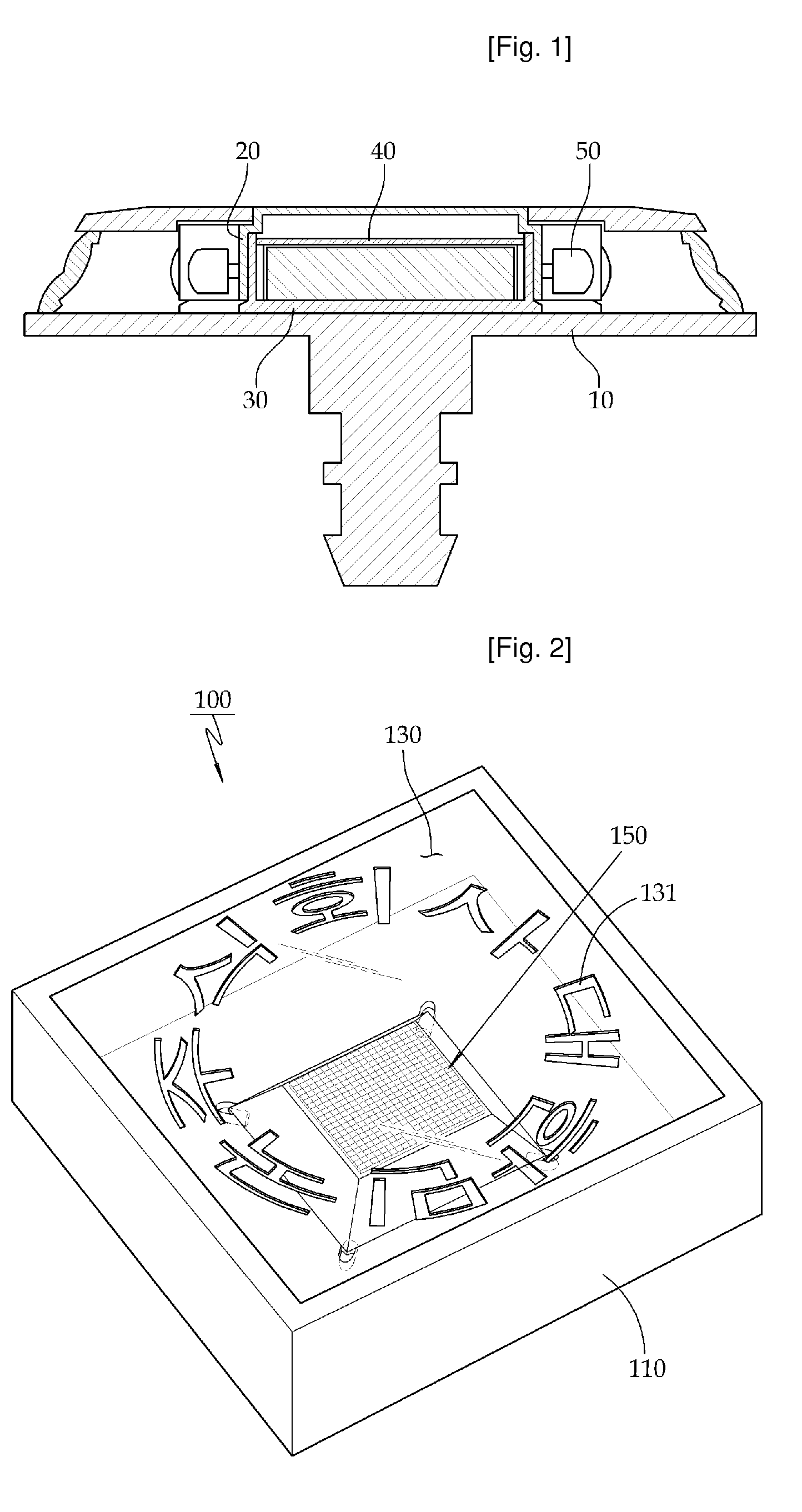
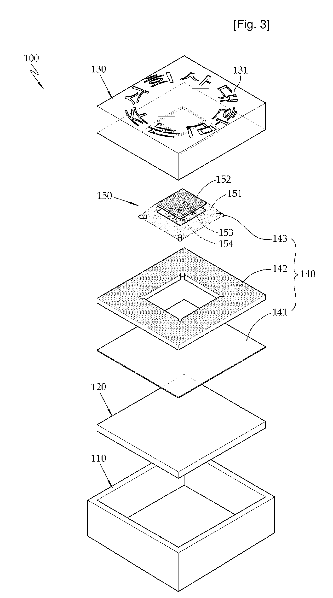
[0019]The light emitting display device equipped with a transparent crystal comprises an outer casing which is embedded under the ground and forms an outer structure; a transparent crystal member which is inserted into the interior of the outer casing and reflects light using a reflection mirror effect of an inner vertical wall surface of the same; a solar cell module which is impregnated into a space formed at a center lower surface of the transparent crystal member with the help of a molding liquid and concentrates a sunshine and converts a light energy into an electrical energy and changes the same; and a light emitting unit which is engaged at a lower surface of a surrounding portion of the transparent crystal member and emits light to the outside based on a power supply by means of the sunshine or the solar cell module.

[0020]A display information such as a character or an image is etched on the transparent crystal member.

[0021]There is further provided a safety member at an inn...


PUM


Abstract

A light emitting display device equipped with a transparent crystal is disclosed which comprises an outer casing which is embedded under the ground and forms an outer structure; a transparent crystal member which is inserted into the interior of the outer casing and reflects light using a reflection mirror effect of an inner vertical wall surface of the same; a solar cell module which is impregnated into a space formed at a center lower surface of the transparent crystal member with the help of a molding liquid and concentrates a sunshine and converts a light energy into an electrical energy and changes the same; and a light emitting unit which is engaged at a lower surface of a surrounding portion of the transparent crystal member and emits light to the outside based on a power supply by means of the sunshine or the solar cell module.

Description

TECHNICAL FIELD[0001]The present invention relates to a light emitting display device equipped with a transparent crystal, and in particular to a light emitting display device equipped with a transparent crystal in which a solar cell module is provided in the interior of a transparent crystal, and an electric energy is charged by concentrating light during a daytime irrespective of an inclination of light emitted into a solar cell, and a light emitting device emits a light via a light spreading embossing guide plate based on the charged electric energy, so that it is possible to more clearly display a certain information such as a character or image etched on a transparent crystal.BACKGROUND ART[0002]A conventional display device is widely used using a light source for displaying various characters or patterns based on an optical fiber. The above display device needs a power supply source for supplying power to a light source. When it is needed to installed at a road, a building, a ...

Claims


Application Information

Patent Timeline
Patent Type & Authority Applications(United States)
IPC IPC(8): G09F13/04
CPCG09F19/22G09F13/20G09F27/007G09F2019/223Y02E10/50
Inventor RYU, JAE-HAK
Owner HAE SUNG SOLAR
Why Eureka
Try Eureka