
Method for defining regions in reservoir simulation

a reservoir simulation and region technology, applied in seismology for waterlogging, instruments, borehole/well accessories, etc., can solve the problems of simplistic simulating fracturing and geomechanics, and restrictive methods

Active Publication Date: 2009-10-08
SCHLUMBERGER TECH CORP
View PDF3 Cites 14 Cited by
  • Summary
  • Abstract
  • Description
  • Claims
  • Application Information

AI Technical Summary

Benefits of technology

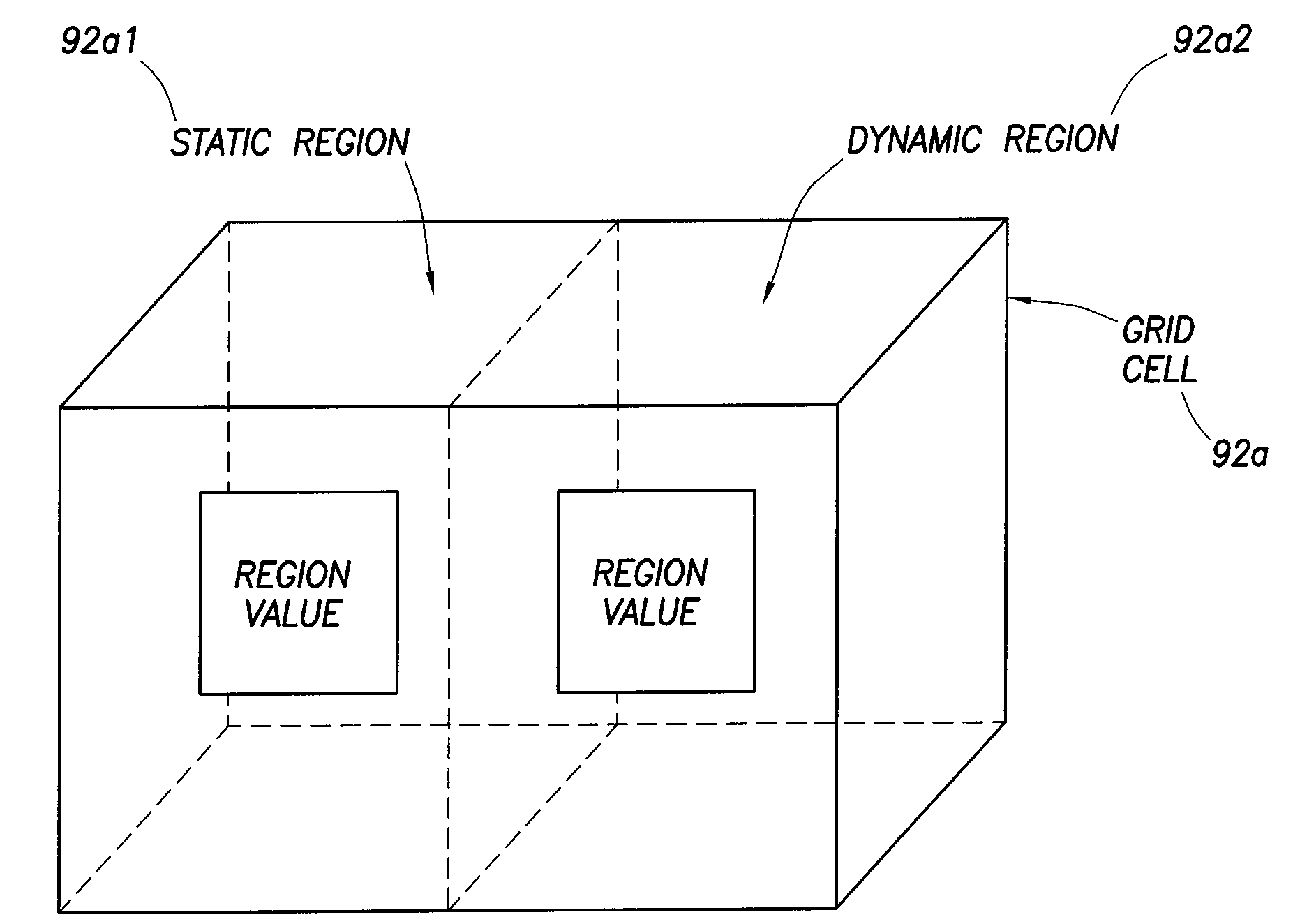
[0006]One aspect of the present invention involves a method practiced by a reservoir simulator for simulating a reservoir and generating a set of simulation results, the simulation results including a framework, the framework further including a plurality of grid cells, comprising: generating one or more static and d

Problems solved by technology

However, the aforementioned ‘method for simulating fracturing and geomechanics’ is extremely simplistic, and very restrictive.

Method used


Image

  • Method for defining regions in reservoir simulation
  • Method for defining regions in reservoir simulation
  • Method for defining regions in reservoir simulation

Examples


Embodiment Construction

[0026]This specification discloses a ‘Method for Defining Regions in Reservoir Simulation’, including an associated system and program storage device and computer program, which would allow a user to define ‘regions’ in a reservoir simulator, where the ‘regions’ are based on complex logical definitions that can be statically and / or dynamically defined. This will allow ‘property and reporting regions’ to be defined and altered, throughout the simulation run, by a user supplied definition. For instance, since each ‘fluid’ has a corresponding ‘property’, the ‘Method for Defining Regions in Reservoir Simulation’ disclosed in this specification would allow the ‘properties of a fluid’ to follow its corresponding ‘fluid’. In addition, the ‘Method for Defining Regions in Reservoir Simulation’ disclosed in this specification could also be useful to focus on an area of a model in order to visualize all the grid blocks whose fluid moves towards the well (focusing on the drainage radius for a p...


PUM


Abstract

A method is disclosed, which is practiced by a reservoir simulator, for simulating a reservoir and generating a set of simulation results, the simulation results including a framework, the framework further including a plurality of grid cells, comprising: generating one or more static and dynamic regions within the grid cells of the framework of the simulation results, the static and dynamic regions each having region values, wherein the region values of the static regions cannot be allowed to change dynamically, and wherein the region values of the dynamic regions can be allowed to change dynamically.

Description

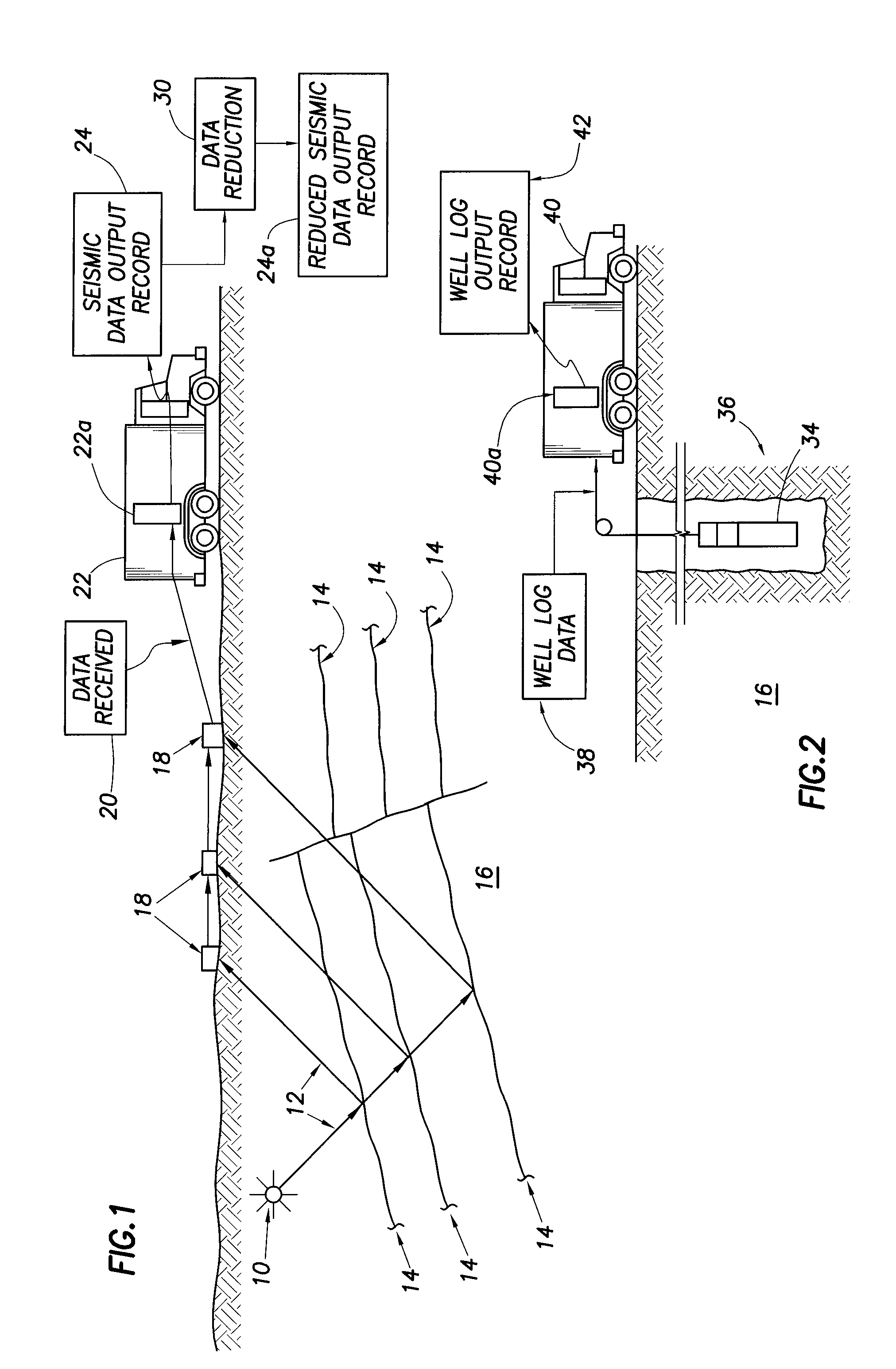
BACKGROUND[0001]The subject matter set forth in this specification relates to a method, including a corresponding system and program storage device and computer program, for defining ‘regions’, both static and dynamic, in reservoir simulation, the ‘regions’ being based on complex logical definitions which can be both statically and / or dynamically defined.[0002]Many clients are interested in a ‘method for simulating fracturing and geomechanics’. This type of simulation can currently be attempted by altering rock and grid properties in a reservoir simulator (for instance, transmissibilities) on a user-specified cell-by-cell basis. However, the aforementioned ‘method for simulating fracturing and geomechanics’ is extremely simplistic, and very restrictive.[0003]This specification discloses a ‘Method for Defining Regions in Reservoir Simulation’, including an associated system and program storage device and computer program, which would allow a user to define ‘regions’ in a reservoir si...

Claims


Application Information

Patent Timeline
IPC IPC(8): G06G7/50
CPCG01V2210/66G01V1/282E21B49/00
Inventor MORTON, ALISONPRIESTLEY, ANDREW
Owner SCHLUMBERGER TECH CORP
Learn More