Radiating fin

a technology of radiating fins and fins, which is applied in the direction of basic electric elements, semiconductor devices, lighting and heating apparatus, etc., can solve the problems of large amount of waste materials produced in the manufacturing process, large amount of electrical elements that generate heat, and complicated and laborious manufacturing of radiating fins, so as to reduce waste, reduce manufacturing costs, and improve the effect of heat radiating

Inactive Publication Date: 2009-10-15
ASIA VITAL COMPONENTS SHENZHEN CO LTD
View PDF7 Cites 3 Cited by
  • Summary
  • Abstract
  • Description
  • Claims
  • Application Information

AI Technical Summary

Benefits of technology

[0006]It is a primary object of the present invention to provide a radiating fin which may be manufactured without wasting too much material.
[0007]Another object of the present invention is to provide a radiating fin that can be more quickly manufactured at reduced time and labor to enable lowered manufacturing cost thereof.
[0011]In brief, the radiating fin of the present invention provides the following advantages: (1) reduced scrap, (2) reduced manufacturing cost, (3) improved heat radiating effect, and (4) enabling firm connection of two radiating fin to one another.

Problems solved by technology

These electronic elements would generate a large amount of heat during the operation thereof.
It is complicated and laborious to manufacture the radiating fins 11 while there is a high bad yield.
Further, a large amount of waste materials are produced in the manufacturing process.
All the above factors result in increased manufacturing cost of the radiating fins 11.
In brief, the conventional radiating fins have the following disadvantages: (1) producing a large amount of scrap, (2) failing to firmly connect to one another, (3) requiring increased time and labor to manufacture and therefore high manufacturing cost, and (4) subjecting to deformation under an external force.

Method used


Image

  • Radiating fin
  • Radiating fin
  • Radiating fin

Examples


Embodiment Construction

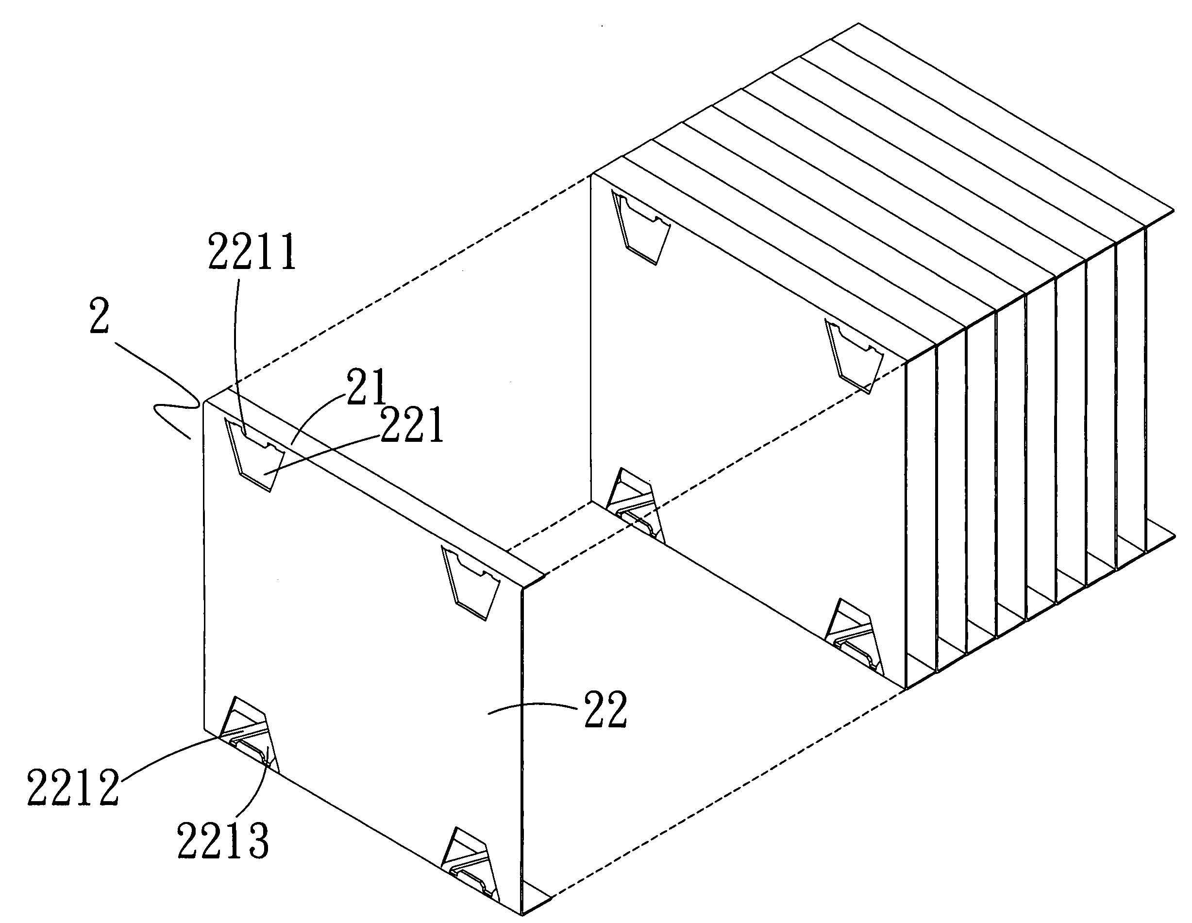
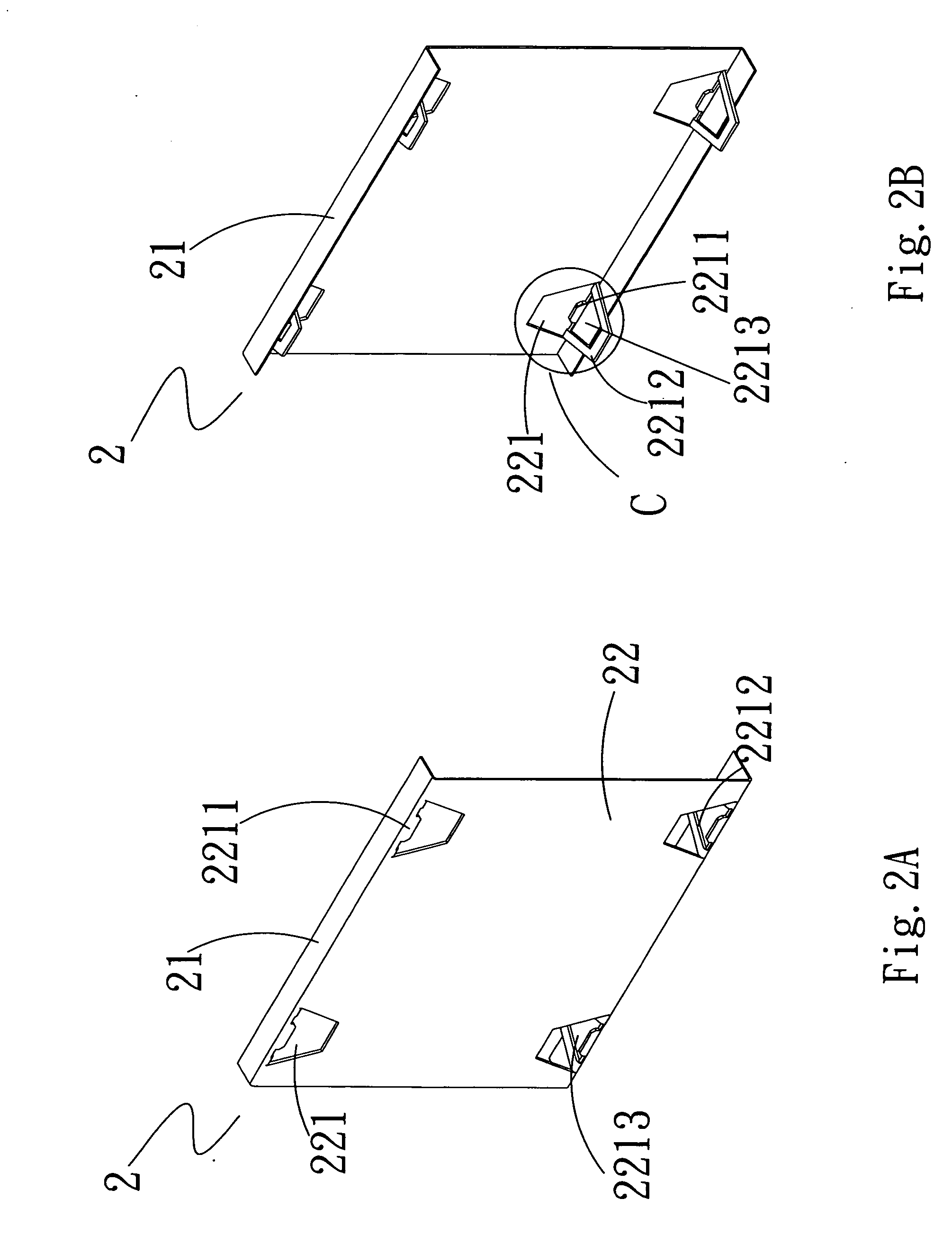
[0024]Please refer to FIGS. 2A and 2B that are front and rear perspective views, respectively, of a radiating fin 2 according to a preferred embodiment of the present invention, and to FIG. 2C that is an enlarged view of the circled area C of FIG. 2B. As shown, the radiating fin 2 of the present invention is made of a sheet material, and includes a flat surface 22 and two rearward extended flanges 21 formed along two opposite edges of the flat surface 22. The flat surface 22 is provided along the two edges adjacent to the flanges with a plurality of openings 221 each. In the preferred embodiment, each of the openings 221 has a trapezoidal configuration with a long base thereof adjacent to the flange 21. A lug 2211 is inward extended from the long base of the trapezoidal opening 221 by a short distance to locate in the same plane as the flat surface 22. In addition, a catch 2212 is rearward extended from the long base of the opening 221. In a preferred embodiment, the catch 2212 is a...


PUM


Abstract

A radiating fin has a flat surface and two rearward extended flanges formed along two opposite edges of the flat surface. The flat surface is formed with a plurality of openings, through which airflow can flow to carry away heat absorbed by the radiating fin. A lug is inward extended from one side of each of the openings adjacent to the flange to locate in the same plane as the flat surface, and a catch in the form of a frame is rearward extended from each of the openings with two lateral sides of the catch spaced from two lateral ends of the lug. When a second radiating fin is connected to a front side of a first radiating fin, the lugs on the first radiating fin are caught in the catches on the second radiating fin, bringing the two radiating fins to firmly assemble together.

Description

FIELD OF THE INVENTION[0001]The present invention relates to a radiating fin, and more particularly to a radiating fin formed with a plurality of openings, from one side of each of the openings a lug is inward extended and a catch is rearward extended. When two radiating fins are assembled together, the lugs on a rear radiating fin are caught in the catches on a front radiating fin.BACKGROUND OF THE INVENTION[0002]Various powerful electronic elements have been developed and applied to high-tech fields. These electronic elements would generate a large amount of heat during the operation thereof. In order to efficiently dissipate the heat generated by the powerful electronic elements, various types of thermal modules with stacked radiating fins have been widely adopted.[0003]FIG. 1 shows a conventional thermal module 1 composed of a plurality of stacked radiating fins 11. Each of the radiating fins 11 has a flat surface 112 and two rearward extended flanges 111 formed along two opposi...

Claims


Application Information

Patent Timeline
Patent Type & Authority Applications(United States)
IPC IPC(8): F28F3/02
CPCH01L23/3672H01L23/4093H01L2924/0002H01L2924/00
Inventor FENG, HUAN-XIAO
Owner ASIA VITAL COMPONENTS SHENZHEN CO LTD
Why Eureka
Try Eureka