Symmetrical matrix representation of dipole UWB antenna

Inactive Publication Date: 2009-10-15
KINSUN INDS
View PDF1 Cites 12 Cited by
  • Summary
  • Abstract
  • Description
  • Claims
  • Application Information

AI Technical Summary

Benefits of technology

[0006]Another purpose for the present invention is to easily and simply mass productions and improving the yield by the structure setting on the substrate.
[0007]Yet another purpose for the present inventi

Problems solved by technology

However; the popular built-in antenna sacrificed its bandwidth and radiation efficiency in order to benefit from its size shrink, said antenna is of bad

Method used


Image

  • Symmetrical matrix representation of dipole UWB antenna
  • Symmetrical matrix representation of dipole UWB antenna
  • Symmetrical matrix representation of dipole UWB antenna

Examples


first embodiment

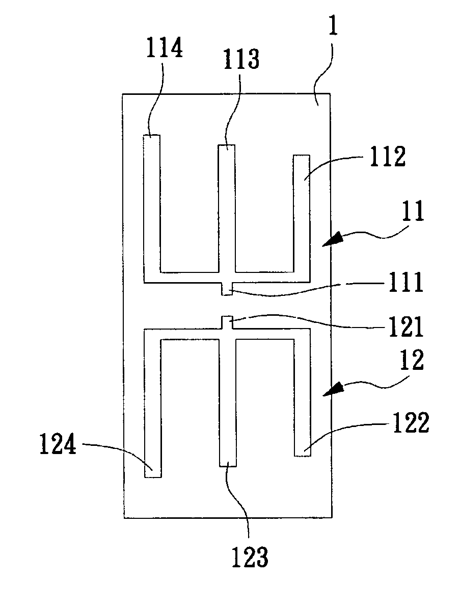
[0016]Turning now to the drawings, FIG. 1 illustrates the symmetrical matrix representation of dipole UWB antenna. It is attachable to wireless communication apparatus, and the symmetrical matrix representation of dipole UWB antenna is mounted on a substrate 1, said substrate 1 is selected from a PCB and metal radiation slice therefore its manufacturing cost is lower than conventional cylinder antenna or spiral antenna. Meanwhile, it is thinner, lighter, shorter, and smaller than prior-art antenna. Said antenna comprises: A first radiation arm 11, 11 comprises a first feed port 111, a first branch 112, a second branch 113 and a third branch 114. 112, 113, and 114 are parallel to each other. 11 and 113 are aligned; a second radiation arm 12, 12 comprises a second feed port 121, a fourth branch 122, a fifth branch 123 and a sixth branch 124. 122, 123, and 124 are parallel to each other. Said 12 and said 121 are aligned; said 111 and said 121 are used to interconnect to wireless commun...

second embodiment

[0020]Referring to FIG. 3, it relates to the symmetrical matrix representation of dipole UWB antenna. The antenna structure on PCB 2 comprises: a first radiation arm 21, said 21 comprises a first feed point 211, a first branch 212, a second branch 213, and a third branch 214; a second radiation arm 22, said 22 comprises a second feed point 221, a fourth branch 222, a fifth branch 223, and a sixth branch 224. Compared with FIG. 1, the most significant different is that the 1st branch 212 and the 3rd branch 214 on the 1st radiation arm 21 are both shorter than the 2nd branch 213. Also, the 4th branch 222 and the 6th branch 224 are both shorter than the 5th branch 223. Said all six branches are wider than those illustrated in FIG. 1. To change the length or width of the 1st radiation arm and the 2nd radiation arm can affect the waveform of antenna frequency response.

third embodiment

[0021]Also referring to FIG. 4, it relates to the symmetrical matrix representation of dipole UWB antenna. The antenna on the substrate comprises: a first radiation arm 31, 31 comprises a 1st feed point 311, a 1st branch 312, a second branch 313 and the 3rd branch 314; a 2nd radiation arm 32, 32 comprises a 2nd feed point 321, a 4th branch 322, a 5th branch 323 and the 6th branch 324. Compared with FIG. 1, the most significant different is that the width for the six branches is wider than that disclosed in FIG. 1 in order to meet the specific demand for antenna feed point of electronic products.


PUM


Abstract

A symmetrical matrix representation of dipole UWB antenna, mounted on a substrate and attachable to a wireless communication apparatus, comprises a first radiation arm, said first radiation arm comprising a first feed point, a first branch, a second branch, and a third branch, said first branch, said second branch, and said third branch are spaced in parallel, said first feed point and said second branch are aligned; and a second radiation arm, said second radiation arm comprising a second feed point, a fourth branch, a fifth branch, and a sixth branch, said fourth branch, said fifth branch, and said sixth branch are spaced in parallel, said first feed point and said second branch are aligned; wherein said first feed point and said second feed point are interconnected to a wireless communication apparatus.

Description

BACKGROUND OF THE INVENTION[0001]1. Field of the Invention[0002]The present invention related to a symmetrical matrix representation of dipole UWB antenna and, more particularly, to the antenna mounted upon a substrate. Said antenna comprising a first radiation arm and a second radiation arm, and the width and the length of said first radiation arm and said second radiation arm are designed according to frequency response match demand.[0003]2. Description of the Related Art[0004]As the modern communication technology gets ahead, wireless communication devices are largely used in notebooks, cellular phones and PDA to serve the wireless communication purposes. In general, wireless communication devices will use built-in antenna due to their prettier outlooks. However; the popular built-in antenna sacrificed its bandwidth and radiation efficiency in order to benefit from its size shrink, said antenna is of bad characteristics and uneasy to adjust to the certain frequency response for t...

Claims


Application Information

Patent Timeline
IPC IPC(8): H01Q9/16
CPCH01Q1/2258H01Q5/371H01Q5/25H01Q9/285
Inventor KAN, CHING-NENGKUO, HSUAN-YI
Owner KINSUN INDS
Why Eureka
Try Eureka