
Processor for Electronic Endoscope, Videoscope, and Electronic Endoscope Apparatus

Active Publication Date: 2009-10-15
HOYA CORP
View PDF19 Cites 53 Cited by
  • Summary
  • Abstract
  • Description
  • Claims
  • Application Information

AI Technical Summary

Benefits of technology

[0007]Aspects of the present invention are advantageous to provide one or more processors for an electronic endoscope each of which makes it possible to display on a monitor an observed image with an appropriate color tone, even though the processor is connected with a videoscope configured to perform color adjustment adapted to a light source of a different type from a light source loaded in the processor.

Problems solved by technology

However, most of existing videoscopes are designed just for the xenon lamp, and have only color adjustment data adapted to the xenon lamp.
Thereby, it is unfortunate that a yellowish observed image is obtained.
It leads to a problem that the existing medical resources cannot be effectively utilized.

Method used


Image

  • Processor for Electronic Endoscope, Videoscope, and Electronic Endoscope Apparatus
  • Processor for Electronic Endoscope, Videoscope, and Electronic Endoscope Apparatus
  • Processor for Electronic Endoscope, Videoscope, and Electronic Endoscope Apparatus

Examples


first embodiment

[0035]Hereinafter, an electronic endoscope apparatus in a first embodiment according to aspects of the present invention will be described with reference to the accompanying drawings.

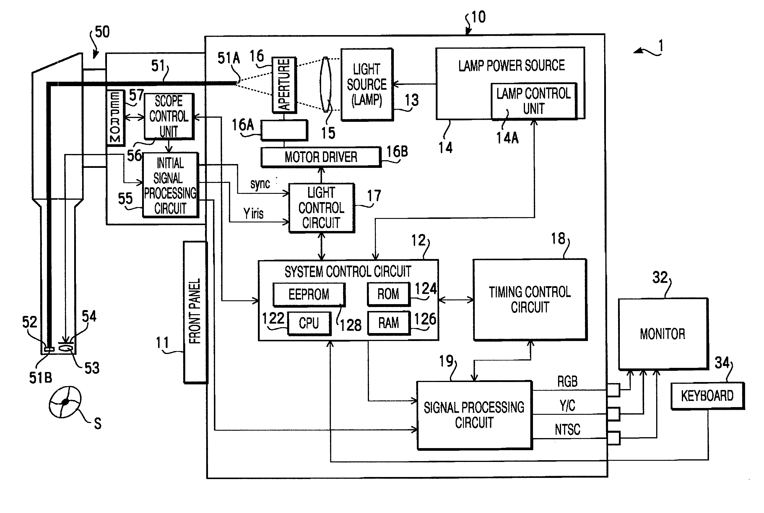
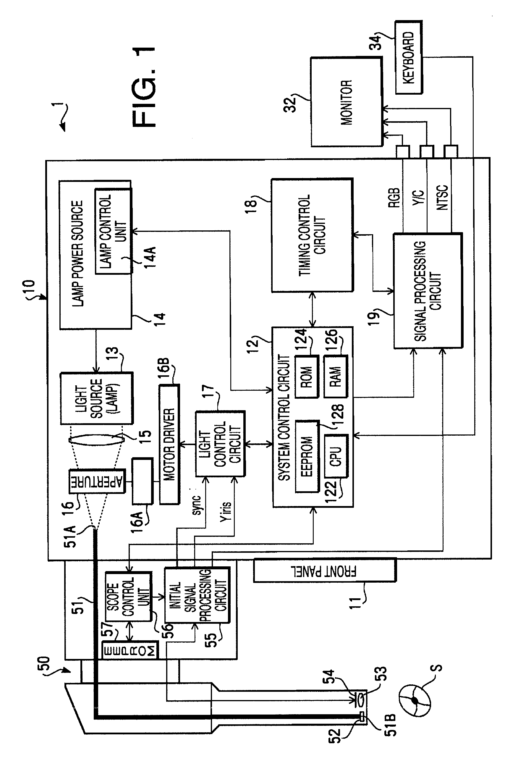
[0036]FIG. 1 is a block diagram of an electronic endoscope apparatus 1 in a first embodiment according to aspects of the present invention. The electronic endoscope apparatus 1 is configured to perform inspections and operations of internal organs such as a stomach.

[0037]The electronic endoscope apparatus 1 includes a videoscope 50 with a CCD 54 as an image sensor provided at the distal end thereof, a processor 10 configured to process a picture signal received from the videoscope 50, a monitor 32 configured to display thereon an image of an observed region, and a keyboard 34 through which an operator inputs information such as the name of the examined subject into the electronic endoscope apparatus 1. The videoscope 50, the monitor 32 and the keyboard 34 are detachably attached to the processor 10, res...

second embodiment

The Second Embodiment

[0068]Subsequently, a second embodiment according to aspects of the present invention will be explained. A configuration of an electronic endoscope apparatus in the second embodiment is substantially identical to that in the first embodiment. However, data areas in the second embodiment which are secured on the EEPROM 57 provided within the videoscope 50 and the EEPROM 128 provided within the system control circuit 12 of the processor 10, and data stored on the EEPROM 57 and the EEPROM 128 are different from those in the first embodiment.

[0069]FIG. 7 shows memory areas for the color adjustment data that are assigned on the EEPROM 57 of the videoscope 50 in the second embodiment, and data stored in the memory areas in an initial state. In the same manner as the first embodiment (see FIG. 3), the color adjustment data for the xenon lamp “KD” is stored in addresses E000h to E00Bh on the EEPROM 57. In the second embodiment, there are secured further data areas (E100...


PUM


Abstract

A processor for an electronic endoscope, which is configured to be connected with a videoscope adapted to generate a picture signal for an image of an observed object through color adjustment using color adjustment data and to transmit the generated picture signal to the processor, the processor includes a light source configured to emit light for illuminating the observed object, a determining unit configured to determine whether the color adjustment data used by the videoscope is adapted to the light source, a color conversion data acquiring unit configured to acquire color conversion data adapted to the color adjustment data when the determining unit determines that the color adjustment data is not adapted to the light source, and a color converter configured to perform color conversion for the picture signal transmitted by the videoscope using the color conversion data acquired by the color conversion data acquiring unit.

Description

BACKGROUND OF THE INVENTION[0001]The following description relates to one or more processors for an electronic endoscope that are connectable with plural types of videoscopes each of which is replaceable relative to the processor and provided with a color adjustment processing device.[0002]An electronic endoscope has been known, which is configured to observe an intended region inside a body with a solid state image sensor inserted into the body such as a charge coupled device (CCD) image sensor. A conventional electronic endoscope includes a cable-shaped videoscope configured to be inserted into the body, and a processor configured to supply, to the videoscope, light for illuminating the observed region inside the body and to convert an image signal received from the videoscope into a video signal through various sorts of processing. Further, the conventional electronic endoscope includes a monitor configured to display thereon an observed image based on the video signal generated ...

Claims


Application Information

Patent Timeline
IPC IPC(8): H04N7/18H04N9/73
CPCH04N5/2256H04N2005/2255H04N9/045H04N5/23209H04N23/555H04N23/56H04N23/663H04N23/84
Inventor TASHIRO, YOSUKE
Owner HOYA CORP
Learn More