Gas detection apparatus using optical waveguide

Inactive Publication Date: 2009-10-15
MITSUMI ELECTRIC CO LTD
View PDF7 Cites 0 Cited by
  • Summary
  • Abstract
  • Description
  • Claims
  • Application Information

AI Technical Summary

Benefits of technology

[0007]The present invention was made in view of the above described circumstances, and it is therefore, a main object of the present invention is to provide a gas detection ap

Problems solved by technology

Thus, it has been difficult to ensure both of the response output and the response speed which decrease according to the increase of the core diameter, at a predetermined level.
Specifically, in response to the existence and non-e

Method used


Image

  • Gas detection apparatus using optical waveguide
  • Gas detection apparatus using optical waveguide
  • Gas detection apparatus using optical waveguide

Examples


Example

MODIFICATION EXAMPLE

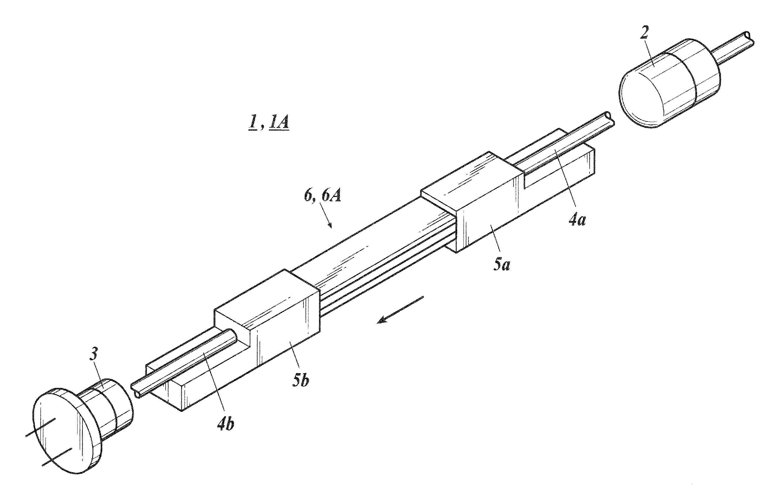
[0059]Subsequently, a gas detection apparatus 1A is described as a modification example of the above explained embodiment. Incidentally, the configuration elements thereof which are similar to those in the above mentioned embodiment are allotted with the same reference numerals, and the description thereof will be omitted.

[0060]The gas detection apparatus 1A comprises an optical waveguide section 6A which is substituted for the optical waveguide 6.

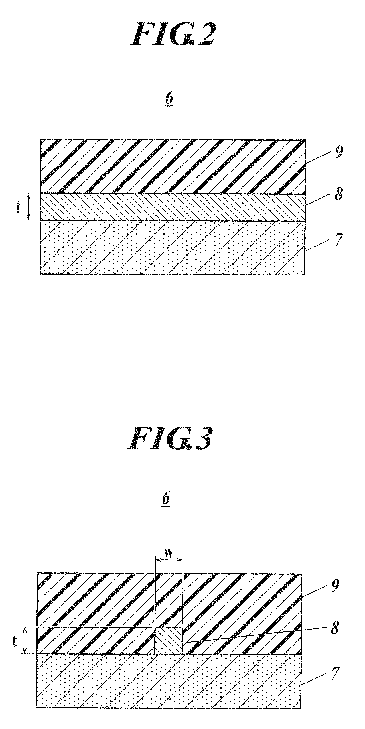
[0061]As shown in FIG. 6, the optical waveguide section 6A comprises four optical waveguides 61A-64A which have four sets of cores 81A-84A and clads 91A-94A on a substrate 7A.

[0062]The cores 81A-84A are formed to have cross-sectional surfaces perpendicular to the light propagation direction, each having a different size, and although they are not particularly limited, the cross-sectional surface of each of the cores is formed to be larger in degree from that of the core 81A to that placed in the lower direction of FIG....

Example

SECOND MODIFICATION EXAMPLE

[0070]Next, a gas detection apparatus 1C is described as a second modification example of the above explained embodiment incidentally, the configuration elements thereof which are similar to those in the above mentioned embodiment are allotted with the same reference numerals, and the description thereof will be omitted.

[0071]As shown in FIG. 9, the gas detection apparatus 1C comprises a light source 2C, a light receiving element 3C, and an optical waveguide section 6C. The optical waveguide section 6C is configured so as to be almost the same as the optical wave guide section 6 in the aforementioned embodiment, but differs in that the substrate 7C is formed so as to be slightly larger than the core 8C and the clad 9C. On the substrate 7C, the light source 2C and the light receiving element 3C are disposed other than the core 8C and clad 9C, and the light 2C and the light receiving element 3C are respectively connected to either of the ends of the core 8C...


PUM


Abstract

Provided is a gas detection apparatus comprising an optical waveguide, wherein the optical waveguide comprises: a core formed on a substrate, the core having a refraction index of n1; and a clad to cover an upper part of the core, the clad having a refraction index of n2, wherein at least one side of a cross-sectional surface of the core, perpendicular to a light propagation direction, is formed by a straight line, and wherein the clad is formed from a sensitive resin which makes a magnitude relation of the refraction index of the core and the refraction index of the clad satisfy n1≦n2 in an atmosphere where a density of a detection gas is less than a predetermined density, and which makes the magnitude relation satisfy n1>n2 in an atmosphere where the density of the detection gas is not less than the predetermined density.

Description

BACKGROUND OF THE INVENTION[0001]1. Field of the Invention[0002]The present invention relates to a gas detection apparatus using an optical waveguide.[0003]2. Description of Related Art[0004]Conventionally, as a sensor to detect a specific gas, a sensor to which an optical plastic fiber is applied is known (see, for example, Japanese Patent Application Laid Open Publication No. 11-44640).[0005]This optical fiber sensor comprises a core in which a refraction index is nCO, and a clad in which a refraction index is nCL. This optical fiber sensor applies the principle in which the magnitude relation of the refraction index nCO and the refraction index nCL reverses by the existence and non-existence of detection gas of a predetermined density. To put it more concretely, first, by a reaction of a sensitive resin which forms the clad with the detection gas, the refraction index nCL is changed from a value which is larger than the refraction index nCO of the core to a value which is smaller...

Claims


Application Information

Patent Timeline
IPC IPC(8): G02B6/00
CPCG01N21/7703G02B6/1221G01N2021/7716
Inventor YAMAGUCHI, SHINYA
Owner MITSUMI ELECTRIC CO LTD
Why Eureka
Try Eureka