Comparator circuit

Active Publication Date: 2020-06-23
ARTERY TECH CO LTD
View PDF5 Cites 0 Cited by
  • Summary
  • Abstract
  • Description
  • Claims
  • Application Information

AI Technical Summary

Benefits of technology

The present invention provides a comparator circuit with the following technical effects: 1. It can improve the performance of an electronic device without causing any side effects or minimizing the likelihood of side effects. 2. It can overcome the tradeoff between speed and power to achieve optimal performance of the electronic device. 3. It can break through the tradeoff between speed and power to deliver instant currents and achieve high response speed. 4. It has both great function and small size compared to related art.

Problems solved by technology

Conventional comparators have certain disadvantages; in particular, a conventional comparator is typically trapped in a tradeoff between speed and power.
In addition, capacitors are required to implement the conventional comparator with a capacitor-coupling dynamic biased architecture, which may reduce area efficiency of the circuit architecture, as well as increasing related costs.
Moreover, the capacitor-coupling dynamic biased comparator needs powerful driving ability regarding its input, and is sensitive to noise and amplitude of input signals.

Method used


Image

  • Comparator circuit
  • Comparator circuit
  • Comparator circuit

Examples


Embodiment Construction

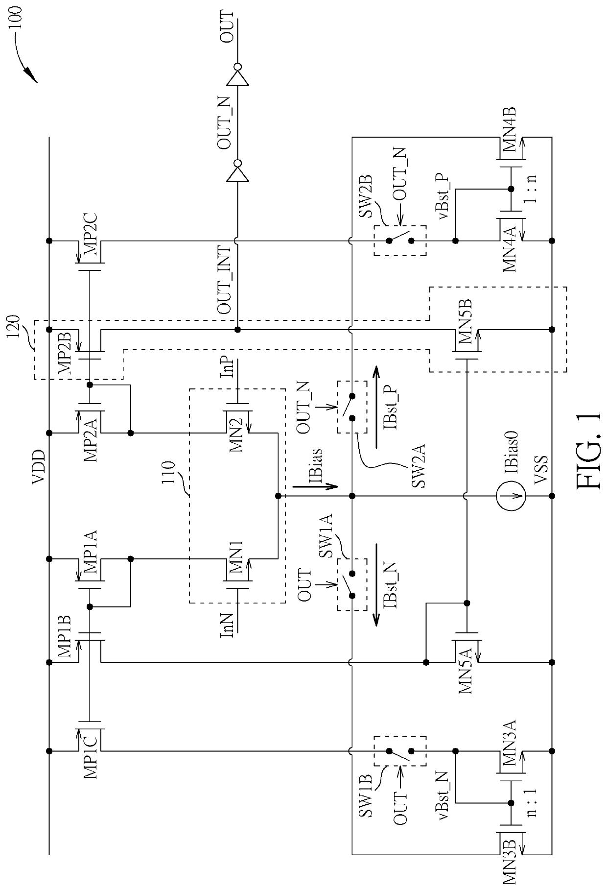
[0016]FIG. 1 is a diagram illustrating a comparator circuit 100 according to an embodiment of the present invention. The comparator circuit 100 may comprise: a comparator coupled between a power voltage VDD and a ground voltage VSS, where the comparator may comprise a plurality of transistors MN1, MN2, MP1A, MP1B, MP2A, MP2B, MN5A and MN5B positioned on a plurality of vertical current paths in the middle of the architecture as shown in FIG. 1, where an input stage 110 of the comparator may comprise transistors MN1 and MN2, and an output stage 120 of the comparator may comprise transistors MP2B and MN5B; a plurality of inverters, coupled to the output stage 120, configured to buffer a comparator output (e.g. an output signal of the output stage 120); a current source generating a current IBias0; and a plurality of positive feedback circuits coupled between the power voltage VDD and the ground voltage VSS, where the positive feedback circuits may comprise a plurality of transistors MP...


PUM


Abstract

A comparator circuit includes: a comparator, coupled between a power voltage and a ground voltage, configured to perform a comparison according to a set of input signals to generate a comparison signal; a current source; and positive feedback circuits. The comparator circuit includes a set of input terminals and sets of transistors respectively coupled between a power voltage and a node or a ground voltage. The positive feedback circuits perform positive feedback operations on the node to generate instant currents on the node, to make the comparator switch the comparison signal in response to transition of the set of input signals in real time. Any of the positive feedback circuits includes: a first switch, configured to enable or disable said any positive feedback circuit in response to transition of the comparison signal; and a set of transistors, configured to generate a second current corresponding to the first current.

Description

BACKGROUND OF THE INVENTION1. Field of the Invention[0001]The present invention is related to electronic circuits, and more particularly, to a comparator circuit.2. Description of the Prior Art[0002]Conventional comparators have certain disadvantages; in particular, a conventional comparator is typically trapped in a tradeoff between speed and power. In addition, capacitors are required to implement the conventional comparator with a capacitor-coupling dynamic biased architecture, which may reduce area efficiency of the circuit architecture, as well as increasing related costs. Moreover, the capacitor-coupling dynamic biased comparator needs powerful driving ability regarding its input, and is sensitive to noise and amplitude of input signals.[0003]Thus, there is a need for a novel architecture to improve overall performance of an electronic system without introducing any side effector in away that is less likely to introduce side effects.SUMMARY OF THE INVENTION[0004]An objective o...

Claims


Application Information

Patent Timeline
IPC IPC(8): H03K5/24
CPCH03K5/2472H03K5/2409H03K5/2481
Inventor HAO, BAOTIANWANG, WEITIELI, CHAO
Owner ARTERY TECH CO LTD
Why Eureka
Try Eureka