
Serializer Architecture for Serial Communications

a serial communication and serializer technology, applied in the field of serial communication, can solve the problems of consuming a significant amount of power in the serial communication network, only being able to adapt to receive parallel data of 2sup>x/sup>bits, and serializers using serial communication that receive b>10/b>-bit parallel data words cannot use such a tree-based scheme directly, so as to reduce power consumption and design complexity.

Inactive Publication Date: 2009-10-15
SEIKO EPSON CORP
View PDF11 Cites 14 Cited by
  • Summary
  • Abstract
  • Description
  • Claims
  • Application Information

AI Technical Summary

Benefits of technology

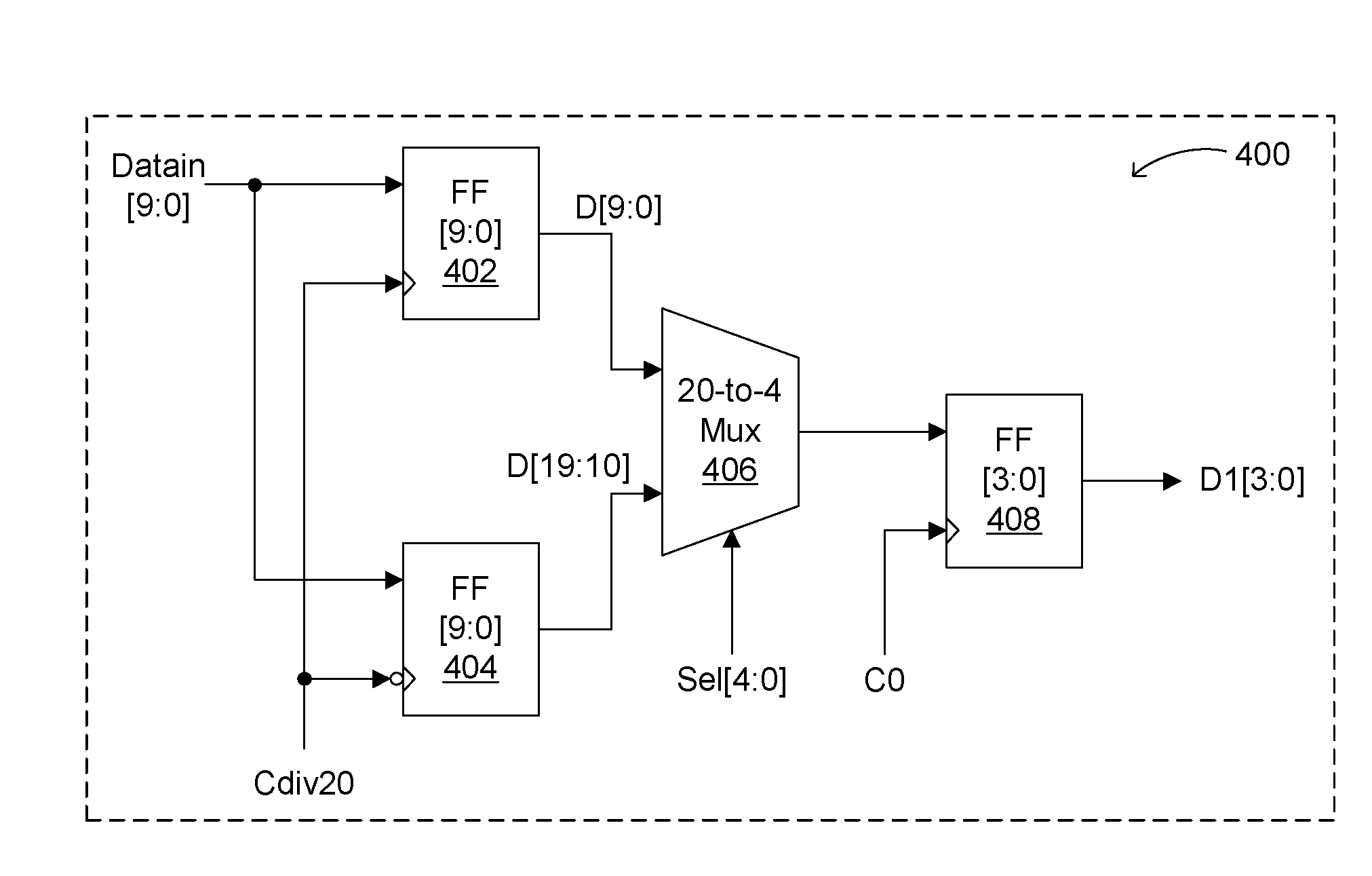
[0011]Embodiments of the present invention can advantageously provide a high-speed serializer approach that utilizes a relatively low-speed first stage coupled to a high-speed (e.g., CML) multiplexer second stage. Further, by using quarter-rate clocking, embodiments of the present invention can result in reduced power consumption and design complexity, as compared to conventional full data-rate clocking serializer architectures. These and other advantages of the present invention will become readily apparent from the detailed description of preferred embodiments below.

Problems solved by technology

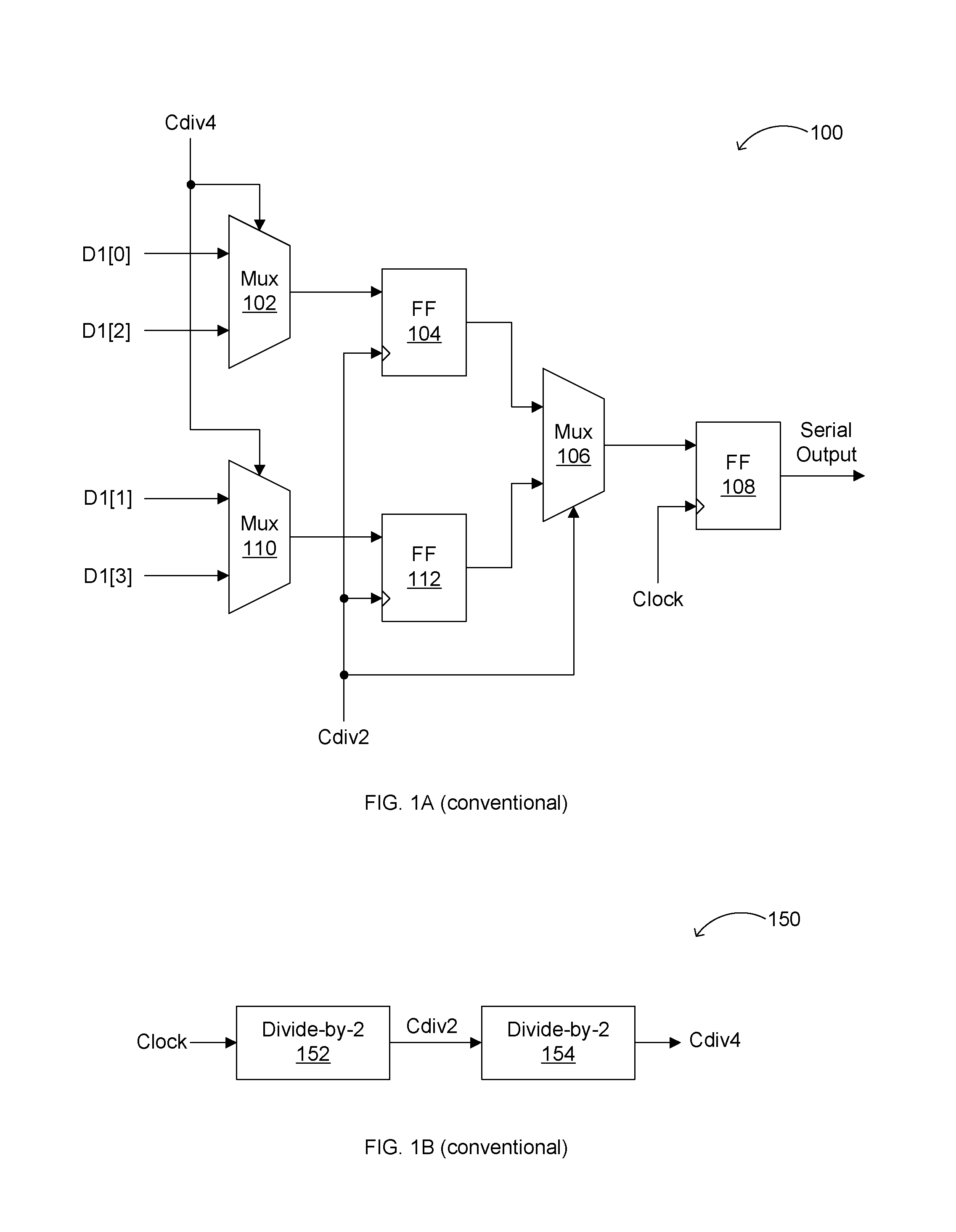
Such a tree-based architecture has the drawback of only being adaptable to receive parallel data of 2x bits, where x≧1.
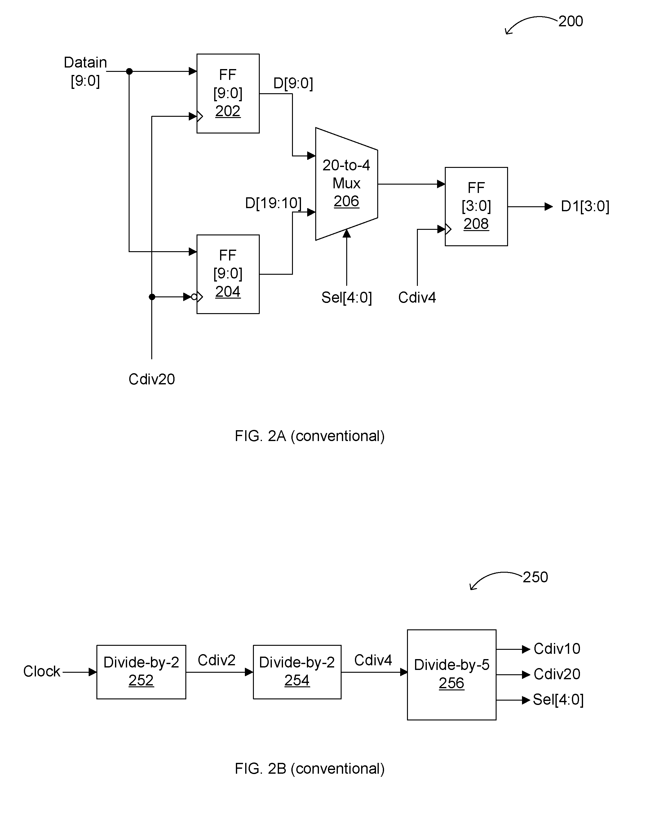
Thus, serializers used in serial communication that receive 10-bit parallel data words cannot use such a tree-based scheme directly.
Serializer circuits operate at the data transmission rate or “data rate,” and thus can consume a significant amount of power in a serial communication network.
In addition, as the data rates of serial communication networks become higher (e.g., into the multi-gigahertz range), it may not be possible for conventional serializer architectures to provide sufficient serialization quality at low power.

Method used


Image

  • Serializer Architecture for Serial Communications
  • Serializer Architecture for Serial Communications
  • Serializer Architecture for Serial Communications

Examples


Embodiment Construction

[0020]Reference will now be made in detail to the preferred embodiments of the invention, examples of which are illustrated in the accompanying drawings. While the invention will be described in conjunction with the preferred embodiments, it will be understood that they are not intended to limit the invention to these embodiments. On the contrary, the invention is intended to cover alternatives, modifications and equivalents that may be included within the spirit and scope of the invention as defined by the appended claims. Furthermore, in the following detailed description of the present invention, numerous specific details are set forth in order to provide a thorough understanding of the present invention. However, it will be readily apparent to one skilled in the art that the present invention may be practiced without these specific details. In other instances, well-known methods, procedures, components, and circuits have not been described in detail so as not to unnecessarily ob...


PUM


Abstract

Methods, algorithms, circuits, and / or systems for serializing parallel data are disclosed. In one embodiment, a serializer can include a first stage configured to convert m-bit-wide parallel data into n-bit-wide parallel data, where n is 2x, m≧2x+y, x is an integer of at least 1, and y is an integer of at least 1, where the first stage includes a memory unit configured to store the m-bit-wide parallel in response to a timing signal and a first multiplexer configured to output the n-bit-wide parallel data in response to a frequency-multiplied derivative of the timing signal, and a current mode logic (CML) multiplexer stage configured to convert the n-bit-wide parallel data into serial data on successive transitions of n phase-shifted versions of the frequency-multiplied derivative of the timing signal.

Description

FIELD OF THE INVENTION[0001]The present invention generally relates to the field of serial communication. More specifically, embodiments of the present invention pertain to methods, circuits, architectures, and / or systems for converting parallel data into serial data.DISCUSSION OF THE BACKGROUND[0002]Serializers or parallel-to-serial converters are widely used in serial communication in order to convert parallel data streams into serial data streams. A serializer is an important component for transmissions in such a communication network, and generally converts a low-speed parallel data signal into a high-speed serial data signal. Thus, in serial communication systems (e.g., 8b / 10b), encoded parallel data is serialized into serial data streams, and transmitted. Typically, in such an exemplary system, the encoded data is a 10-bit parallel data word, and hence a tree-based serializer architecture cannot be employed.[0003]FIG. 1A shows a conventional tree-based serializer architecture ...

Claims


Application Information

Patent Timeline
IPC IPC(8): G06F13/42
CPCH03M9/00H03K5/135
Inventor PADAPARAMBIL, MURALIKUMAR A.
Owner SEIKO EPSON CORP
Learn More