
Building system and method with prefabricated structures joined between them, reusable and transportable

Inactive Publication Date: 2009-10-22
GRAF RODRIGO
View PDF18 Cites 11 Cited by
  • Summary
  • Abstract
  • Description
  • Claims
  • Application Information

AI Technical Summary

Benefits of technology

[0025]It has been seen in the prior art, that obtaining work, help centers, disaster relief centers, living and / or recreation platforms in inhospitable spaces, may be of great economical benefit for users and of great human need in cases, for example of natural disasters.
[0032]Therefore, all the embodiments provide removable joints, making it possible to dismount the prefabricated structures and tow said prefabricated structures easily.
[0033]Therefore, it is an object of the present invention to make a connection or coupling system between different prefabricated structures, with front, back, lateral, upper and lower connections that create a greater livable or usable area.
[0039]Finally, it a another object that the building is easily mountable and dismountable so that it may be easily re-used, transported and conveyed to different locations.

Problems solved by technology

Additionally, this patent does not disclose that the semi-trailers or containers may be towed to dismount the building.
As does the US patent and the French patent, the container of the German patent cannot be towed from the building site, and further, said German patent does not disclose the joining of two or more containers.

Method used


Image

  • Building system and method with prefabricated structures joined between them, reusable and transportable
  • Building system and method with prefabricated structures joined between them, reusable and transportable
  • Building system and method with prefabricated structures joined between them, reusable and transportable

Examples


first embodiment

[0086]As disclosed before, the prefabricated structures 1 of the invention, may include in a first embodiment a first lateral bed 18 and a second lateral bed 19. FIG. 14 is an upper view of the prefabricated structure 1. As disclosed before, the first lateral bed 18 must be in a height different to the main bed 6. Specifically, the height of the two lateral beds 18, 19 must be less than the height of the main bed 6, however, the height between the two lateral beds 18, 19 is preferably different, so that the longitude of the lateral beds 18, 19 is similar to that of the main bed 6 and so that when said lateral beds are in a retracted or embedded position, said beds 18, 19 fit beneath the main bed 6. The lateral beds 18, 19 are extracted towards the exterior in regards to the main bed 6, wherein the first lateral bed 18 is extractable to a first lateral position in regards to the main bed 6, and a second lateral bed 19 is extractable to a second determined position, opposite to the fi...

second embodiment

[0090]FIG. 16 shows the prefabricated structures 1 coupling system. Specifically, the figures shows that the prefabricated structures comprise only a single fixed main bed 6, that is that is not extractable nor telescopic. The fixed main bed 6 has a plurality of tongues 35 which are found in the lateral ends 34 of the main bed 6, or the tongues 35 may be telescopic. That is the edge of the lateral ends 34 of the main bed 6, main have such a configuration, that when naturally coupled with the opposing edge of the other main bed 6, either the tongues may be embedded beneath the main bed 6 or main be telescopic. When the tongues 35 are extracted, these may acquire the same height than the main bed 6 by means of a driven system which creates a normal force over said tongues 35.

[0091]The configuration may be the same as shown in FIG. 16, or may be such, that the back wall 28 and the front wall 31 adopt any shape such that they may be coupled between themselves. The back wall 28 and the f...


PUM


Abstract

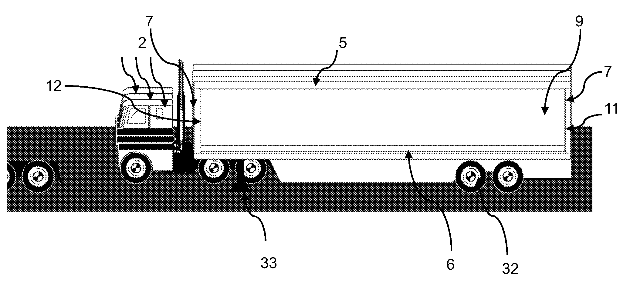
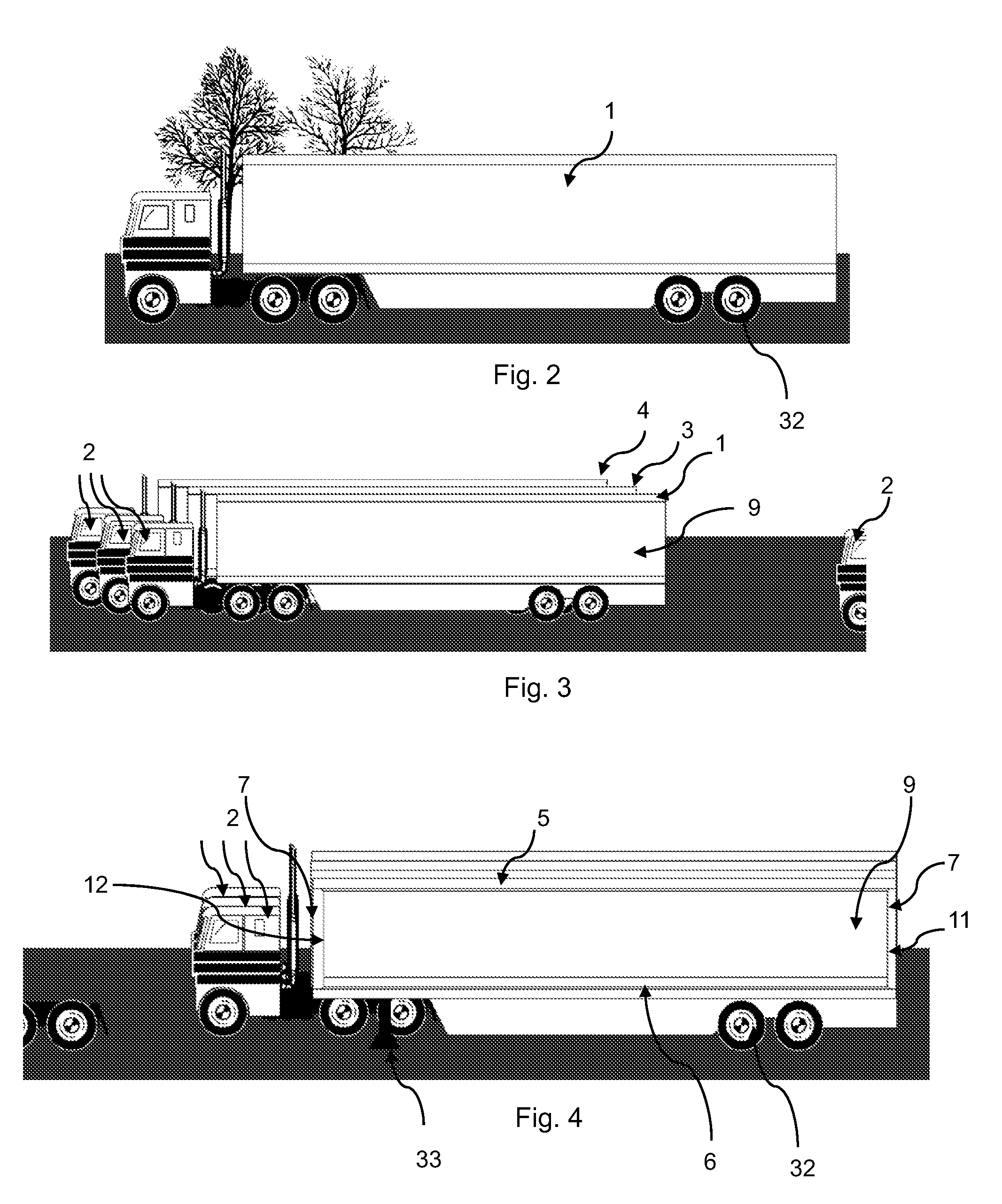
A building system and method by means of at least two prefabricated structures comprising a first prefabricated structure containing at least two lateral walls, a front wall and a back wall; a second prefabricated structure containing at least two lateral walls, a front wall and a back wall; a first transportation axis in which said first prefabricated structure is mounted, capable of towing said first prefabricated structure to a building site and said first transportation axis is parked in the construction site; a second transportation axis in which said second prefabricated structure is mounted, capable of towing said second prefabricated structure to said building site and said second transportation axis is parked in the construction site; at least one of said lateral, back or from wall of each one of said first and second prefabricated structure is dismounted, dismantled or rolled up; wherein said first and second prefabricated structures are joined in such a manner that said prefabricated structures are in communication by said dismounted, dismantled or rolled up side.

Description

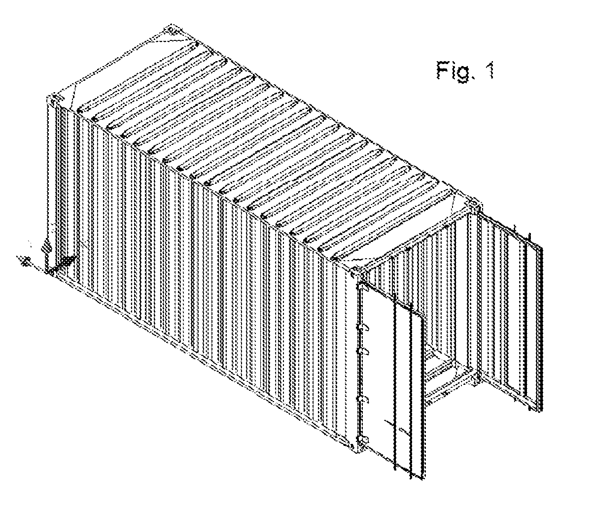
CROSS-RELATED APPLICATIONS [0001]This application claims benefit from U.S. provisional application No. 61 / 046,961 filed on Apr. 22, 2008.FIELD OF THE INVENTION [0002]The present invention is related with prefabricated structures, such as semi-trailer, a shipping container, or any other similar container, that are towed or transported to particular locations; a system for building with said prefabricated structures and a method for creating buildings with said prefabricated structures. More particularly, this invention refers to at least one, and more preferably to two semi-trailers or containers, shipping or other, that are transported over a transportation axis, which when parked proximal between themselves, create a superior surface in regards to itself or other semi-trailers or similar containers, and more particularly to a system and method for joining and dismounting said prefabricated structures in a lateral, front, back, upper and lower manner so as to create a single buildin...

Claims


Application Information

Patent Timeline
IPC IPC(8): E04H5/02E04B1/00E04H1/12E04H5/04
CPCE04B1/34305B61D15/04
Inventor GRAF, RODRIGO
Owner GRAF RODRIGO
Learn More