Current feeding device for wire electrical discharge machining

a current feeding device and wire technology, applied in the direction of current collectors, electrical-based machining electrodes, manufacturing tools, etc., can solve the problems of wire becoming abrasive, the feeder is more prone to mechanical wear, and the overall life of the feeder is thus considerable, and achieves low friction, low wear, and small dimension

Active Publication Date: 2021-04-13
AGIE CHARMILLES
View PDF15 Cites 0 Cited by
  • Summary
  • Abstract
  • Description
  • Claims
  • Application Information

AI Technical Summary

Benefits of technology

[0018]It is an aspect of this invention to provide an improved current feeding device for the reliable supply of electrical current to a wire electrode. In particular, it is an objective to provide a current feeding device having low friction and low wear, which has a small dimension and is easily mountable and dismountable.
[0023]Due to the low friction between the jewel and the rotary electrically conductive body and the unilateral coaxial contacting of the brush with said rotary electrically conductive block, the braking torque is minimized. The particles produced by the machining process cannot seriously compromise the bearing function nor compromise the current feeding to the rotary electrically conductive body by means of the brush. The inventive current feeding device is comparably immune to the any deterioration due to such debris, so that the rotation of the rotary electrically conductive body is ensured, providing a consistent current feeding capability over lifetime, and a long service life.
[0024]Due to the rotation of the rotary electrically conductive body the circumferential position where the current is fed to the wire changes continuously. Thus the heating is distributed in time and space, and the combined thermo-mechanical stress. The jewel bearing has one or more jewels, with the jewels made of sapphire, ceramic, ruby or other suitable hard material. Advantageously, the jewel which is mounted in a jewel retainer has an at least partially spherical shape. On the other hand a jewel seat is formed on the rotary electrically conductive body to receive said jewel, forming the jewel bearing. The seat has an at least partially spherical shape, i.e. a cup shape, or an at least partially conical shape. The aperture angle of an at least partially conical seat is preferably in the range of 60° to 160°, more preferably in the range from 80° to 120°, typically 90°. The sapphire jewel is an electrical insulator so that there is no current flow through the bearing to the rotary electrically conductive body, and thus no damaging due to electrical erosion.
[0030]The rotation of the rotary electrically conductive body is disturbed by the friction of the current feeding brush and the friction of the jewel bearing. The latter is comparably small due the low frictional coefficient μJ of the jewel bearing, whereas the braking action of the current feeding brush against the rotary electrically conductive body is not negligible. The braking force of the brush FBB is proportional to the brush spring force FS urging the brush against the rotary electrically conductive body, and proportional to the frictional coefficient μB of the brush on the rotary electrically conductive body, so that FBB=FS*μB. The breaking force of the jewel bearing FBJ is proportional to the reaction force FRJ which is essentially equivalent to the brush spring force FS, and proportional to the frictional coefficient μJ of the jewel on the rotary electrically conductive body, so that FBJ=FS*μJ. To achieve a very low frictional coefficient μJ the jewel seat is machined with high accuracy and low roughness.
[0032]To achieve a possibly low braking torque TB the jewel seat and the contact surface of the brush on the rotary electrically conductive body are machined with high accuracy and low roughness, and the diameter of the jewel and, in particular, the diameter of the brush are not made unnecessarily large. In particular the diameter of the brush for the feeding of the current to the rotary electrically conductive body is made as small as possible to achieve a low braking torque TB, and as large as needed to transfer the machining current.
[0035]A larger diameter of the rotary electrically conductive body ensures a higher lifetime as a consequence of the larger circumference. Further a larger diameter of the rotary electrically conductive body provides a better safety margin FS, because of the lever effect of the radius rF. However the size of the rotary electrically conductive body also determines the size of its enclosure, respectively the size of the wire guiding heads.

Problems solved by technology

The overall lifetime of the feeder is thus considerable, but due to the wearing the current feeder must be frequently repositioned.
The lower current feeder which lies below the machining area is more prone to mechanical wear, because the wire surface is covered with craters, and work piece particles which are removed by the WEDM process may be transferred to the traveling wire, so that the wire becomes abrasive.
During the WEDM process the electrical discharges are supposed to occur between the wire and the workpiece, but undesired discharges due to unstable contact may occur at the interface area between wire and current feeders.
In the lower head the wire is laced with craters, roughened by the WEDM process, so that instability in the current transfer to wire may be even worse.
Thus the current feeders are subject to combined thermo-mechanical stress, which wears the feeders and limits the lifetime.
Wearing of the current feeder generates a groove in the feeder; the risk of wire breaking increases with the formation of such grooves.
Another problem is given by the braking force generated by the sliding friction over the stationary current feeders.
The cited documents show possible solutions for a rotary current feeder for use in WEDM's, however with certain of these solutions an unhindered rotation of the roller is not guaranteed, due to the friction of a gasket, or the friction of a badly placed contact brush, or the bearing friction.
With certain of these solutions the current flows through a supporting shaft of the rotary current feeder and the bearing is subject to erosion due to discharges occurring in the bearing.
Also, during the wire cutting the machining area is exposed to the erosion particles, which may deposit within the wire guiding heads, and may increase the friction and compromise the operability.
This problem may occur in particular with fine wires or in general in case of low wire electrode tensioning force.
If the continuous rotation is not guaranteed the current supply is unstable and thus unreliable, in which case would be preferable to have a conventional sliding contact.
A solution which includes a motor for the rotation of the current feeder would ensure the reliable rotation, but this is not preferable because of the additional means required, costs, and because of the additional space needed.
A solution including a liquid contact such as mercury is not considered to be viable and thus excluded a priori, because of the technical complication, because of the required space, because of the difficulties in case of the replacement of worn parts and because of the consequences in case of failure.

Method used


Image

  • Current feeding device for wire electrical discharge machining
  • Current feeding device for wire electrical discharge machining
  • Current feeding device for wire electrical discharge machining

Examples


Embodiment Construction

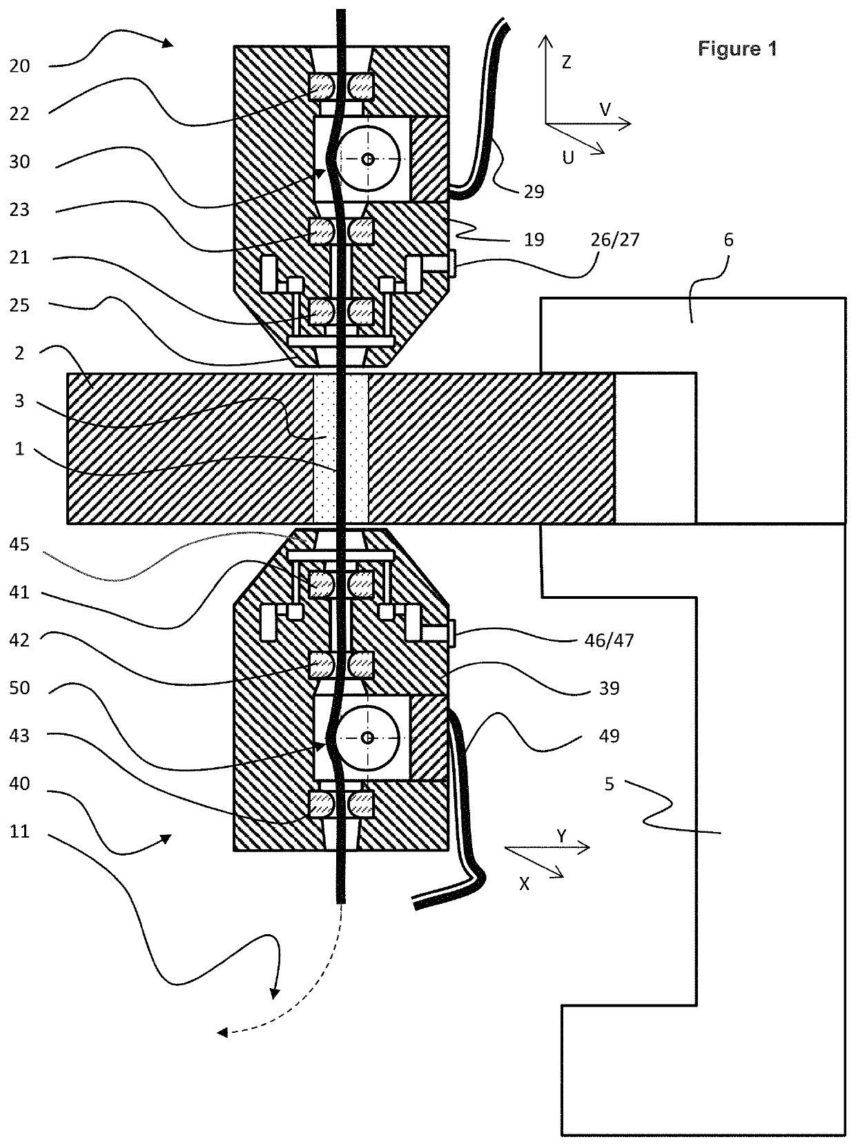
[0045]First, the relevant parts of a WEDM according to the present invention are described with reference to FIG. 1, in a very simplified representation. A workpiece 2 having a starting hole 3 is mounted on a stationary table 5 and fixed by means of a clamp 6. The tensioned wire electrode 1 is guided by means of an upper wire guiding head 20 and a lower wire guiding head 40. The upper and the lower wire guiding heads 20, 40 are moveable in parallel plans with respect to the stationary workpiece 2, by means of the U, V axis for the upper head 20, and by means of the X, Y axes for the lower head 40. The upper wire guiding head 20 is further moveable vertically. The upper and lower wire guiding heads comprise main wire guides 21, 41 which are arranged as close as possible to the workpiece. Further each head comprises a pair of pre-guides, that is, the pre-guides 22 and 23 in the upper head, and the pre-guides 42 and 43 in the lower head. Between the pair of pre-guides there is a rotary...


PUM

PropertyMeasurementUnit
diameteraaaaaaaaaa
diameteraaaaaaaaaa
aperture angleaaaaaaaaaa

Abstract

The present invention is directed to a current feeding device for the supply of electrical current to a wire electrode traveling in an electro-erosion machine during the machining operation. The current feeding device comprising: a rotary electrically conductive body which is in contact with the wire electrode; at least one bearing for supporting the rotary electrically conductive body at one side; and a brush for electrically contacting the rotary electrically conductive body and for supporting the rotary electrically conductive body at the other side of the body and opposite side to the bearing. The brush is at the rotary axis of the rotary electrically conductive body.

Description

CROSS-REFERENCE TO RELATED APPLICATIONS[0001]This application claims the benefit and priority of European Application No. 18 175 477.1, filed Jun. 1, 2018. The entire disclosure of the above application is incorporated herein by reference.FIELD OF THE INVENTION[0002]The present invention relates to a current feeding device for supplying electrical current to a wire electrode on a wire electrical discharge machine.BACKGROUND OF THE INVENTION[0003]Wire electrical discharge machines (WEDM) use a traveling wire electrode as a tool to cut a desired contour into a workpiece with high accuracy. The workpiece is cut by an electrical discharge process in which electrical discharges occur between the wire electrode and the conductive work piece. This process wears the wire which is thus continuously renewed. The new wire electrode is stored on a wire spool and travels under mechanical tension through a wire circuit of the WEDM. In the machining area the wire electrode is precisely guided by m...

Claims


Application Information

Patent Timeline
Patent Type & Authority Patents(United States)
IPC IPC(8): B23H7/10H01R39/64
CPCB23H7/107H01R39/64B23H11/00B23H9/04B23H3/00B23H9/00
Inventor VOLPI, FRANCO
Owner AGIE CHARMILLES
Why Eureka
Try Eureka