Method and Apparatus to Cement A Perforated Casing

a perforated casing and cementing technology, applied in the field of well cementing, can solve the problems of inability to use conventional cement pumping technique inside the permeable screen to be returned through the annulus, and inability to achieve the effect of simple cement annulus cementing method

Active Publication Date: 2009-10-22
SCHLUMBERGER TECH CORP
View PDF12 Cites 76 Cited by
  • Summary
  • Abstract
  • Description
  • Claims
  • Application Information

AI Technical Summary

Benefits of technology

[0016]There are possible configurations of the delivery opening, in a first configuration they ensure that the treatment fluid passes into the annulus via a void making communication with the zones to treat; in a second configuration, they ensure that the treatment fluid passes into the annulus via an element permeable to the material, preferably the permeable element is a part of the tube.
[0017]Preferably also, the apparatus comprises: a deflating means for deflating the sleeve, the deflating means ensuring that the sleeve is no more in contact with the tube.

Problems solved by technology

However, when a permeable screen is present downhole, there is no simple way to cement the annulus.
Effectively, conventional technique where cement is pumped inside the permeable screen to be returned through the annulus will not work, because the cement will pass through the first openings of the permeable screen and no cement will be pumped at the other extremity.
Further cement would fill the inside of the permeable screen and extra drilling, which is costly and time consuming, will be required after the cement is set.
Even this conventional technique does not apply to other types of fluids and there is no simple way to make a treatment to a zone of the borehole behind a permeable screen.

Method used


Image

  • Method and Apparatus to Cement A Perforated Casing
  • Method and Apparatus to Cement A Perforated Casing
  • Method and Apparatus to Cement A Perforated Casing

Examples


first embodiment

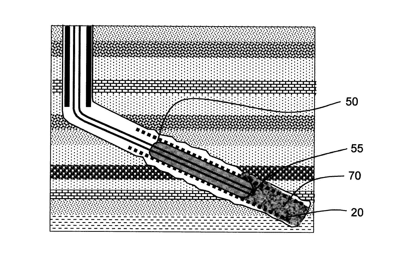
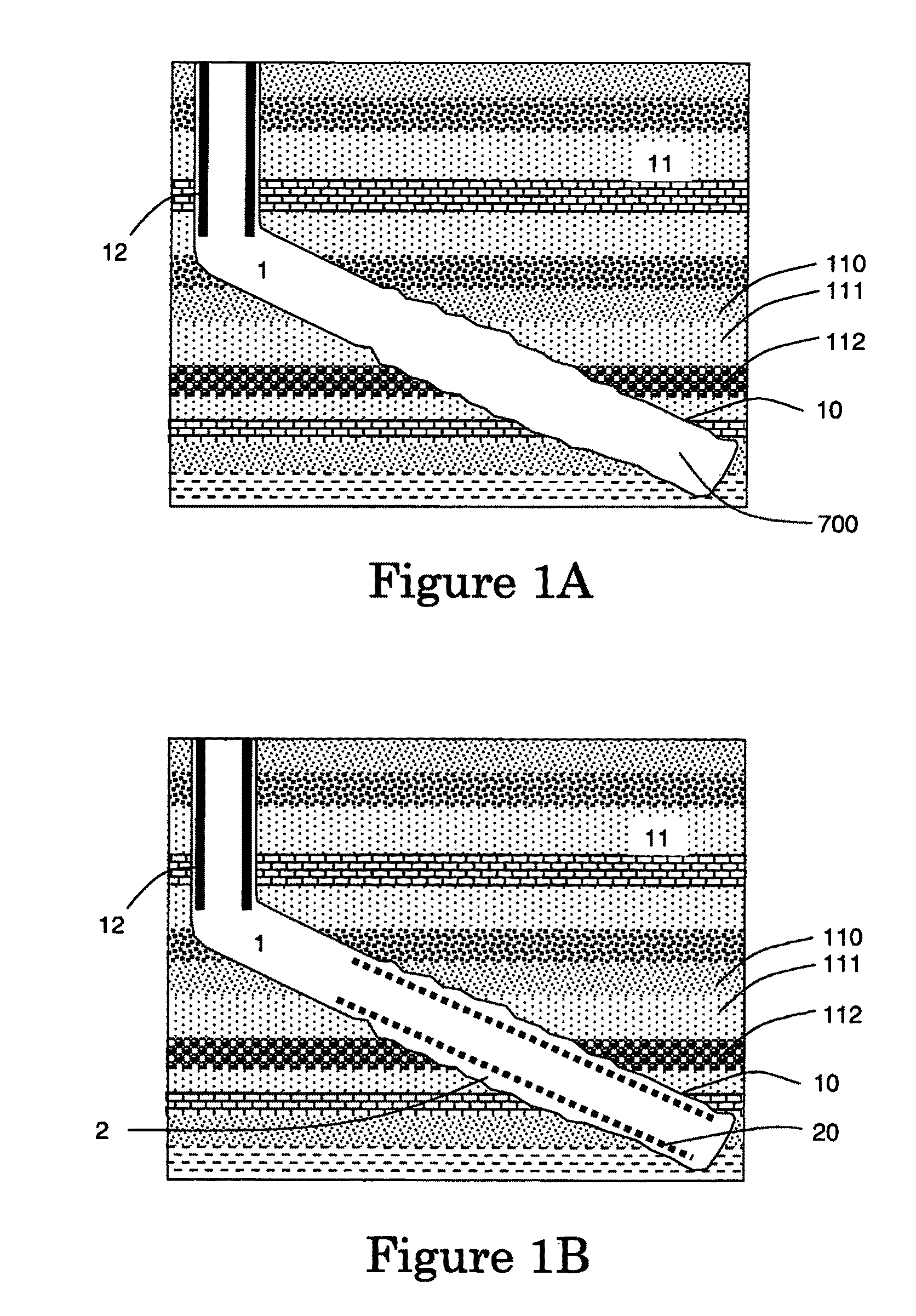
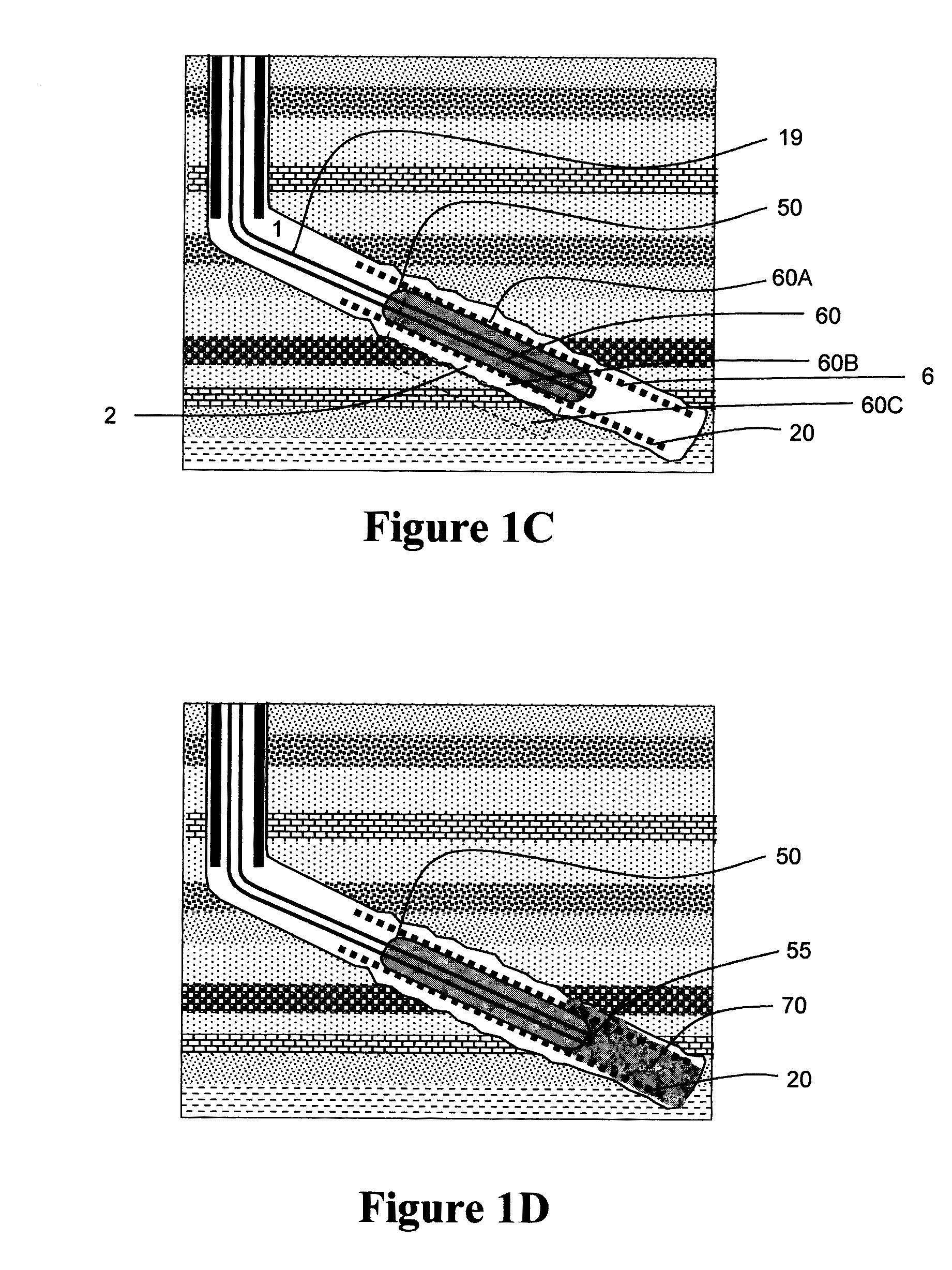
[0046]In a first embodiment, the method and the apparatus according to the invention are deployed at the bottomhole of the well, all the volume of the zone 70A left downhole of the apparatus 40 can be filled with the treatment fluid. After the treatment is finished, if a settable fluid is used, the set fluid remained in zone 70A can be drilled with a drilling tool lowered into the well from the surface.

second embodiment

[0047]In a second embodiment, the method and the apparatus according to the invention are deployed anywhere in the well, the volume of the zone 70A left downhole of the apparatus 40 is unknown and considered big. If the treatment fluid 70 has the same density as the fluid 700 already in the well, there is no risk that the treatment fluid fills first the zone 70A. However, if the treatment fluid 70 has not the same density as the fluid 700 already in the well two solutions can be used. One solution can be to pump few barrels of a viscous fluid into a part of said zone 70A, for example viscous fluid can be viscous bentonite pill, a delayed-gel, a reactive fluids system (RFS). If this is not sufficient, a second solution can be to mechanically isolate a part of said zone 70A with a second apparatus. Said second apparatus will be deployed first and will act as a plug so to limit the zone 70A to a smallest volume. An example of such a second apparatus can be found in U.S. Pat. No. 3,460,...


PUM


Abstract

A method of and an apparatus for treating a near zone and/or a far zone of a well is disclosed. The method comprises the following steps. (1) A tube that is permeable to a material is placed inside a wellbore, forming an annulus inside the wellbore. (2) A setting section surrounded by a sleeve is placed inside the tube. The sleeve is expandable and impermeable to the material. (3) The sleeve is inflated so that the sleeve is in contact with the tube, ensuring for a first zone of the tube is impermeable to the material, but leaving a second zone permeable to the material. (4) A treatment fluid is pumped to the zones that passes through the second zone still permeable to the material. (5) The near zone in the annulus and/or the far zone in the surrounding formation is treated with the treatment fluid.

Description

FIELD OF THE INVENTION[0001]The present invention broadly relates to well cementing. More particularly the invention relates to servicing apparatus for completing downhole wells from a subterranean reservoir, such as for instance an oil and gas reservoir or a water reservoir.DESCRIPTION OF THE PRIOR ART[0002]After a well has been drilled, the conventional practice in the oil industry consists in filing the well with a metal casing. The casing is lowered down the hole and cement is pumped inside the casing and returns through the annulus where it is allowed to set. Lining the well aims at a dual purpose: preventing the bore walls from collapsing and isolating the various geological strata and thus, avoiding exchange of fluids between them. Furthermore, it can be useful also for different reasons to fill the well with a permeable screen (meaning not impermeable as metal casing) as perforated tubular, tubular with other openings, slotted liner or expandable screen. Use of such permeabl...

Claims


Application Information

Patent Timeline
Patent Type & Authority Applications(United States)
IPC IPC(8): E21B43/16E21B33/00
CPCE21B33/1275E21B43/25E21B43/082E21B33/127E21B33/134E21B33/14E21B43/08E21B43/261
Inventor GAMBIER, PHILIPPEJAMES, SIMONRAYSSIGUIER, CHRISTOPHE
Owner SCHLUMBERGER TECH CORP
Why Eureka
Try Eureka