
Eureka
For R&D, Eureka makes reading and utilizing patents & technical documents easy.
Eureka AIR
Designed for self-driven R&D workflows. Generate viable solutions, solve complex R&D challenges, empower your innovation with AI.

Eureka Materials
Designed for material experts only. Revolutionize your material R&D, from search, analyze, to developing new materials.

TechResearch
Generate reliable direction feasibility study reports for your R&D in just a few steps.

TechSeek
Discover and master advanced knowledge NOW. Basics, ideas, possibilities, all at once.

TechMind
As an expert in R&D Theories, TechMind can generates customized viable solutions instantly.

TechRisk
Analyze your overall solution with one click, know your potential R&D risks in advance.

TechMonitor
Get weekly tech updates, stay abreast of the latest tech innovations and key insights.
Position measuring apparatus
- Summary
- Abstract
- Description
- Claims
- Application Information
AI Technical Summary
Benefits of technology
Problems solved by technology
Method used
Image

Examples
Embodiment Construction
[0028]In accordance with embodiments of the present invention, an improved position measuring apparatus is provided which includes: (a) a bearing, (b) a rod guided in the bearing, (c) a linear magnetic field sensor, and (d) a magnet. As discussed in greater detail hereinafter, the rod includes a cutout, and the magnet is arranged in the cutout inside an enveloping cylinder lateral surface around the rod.
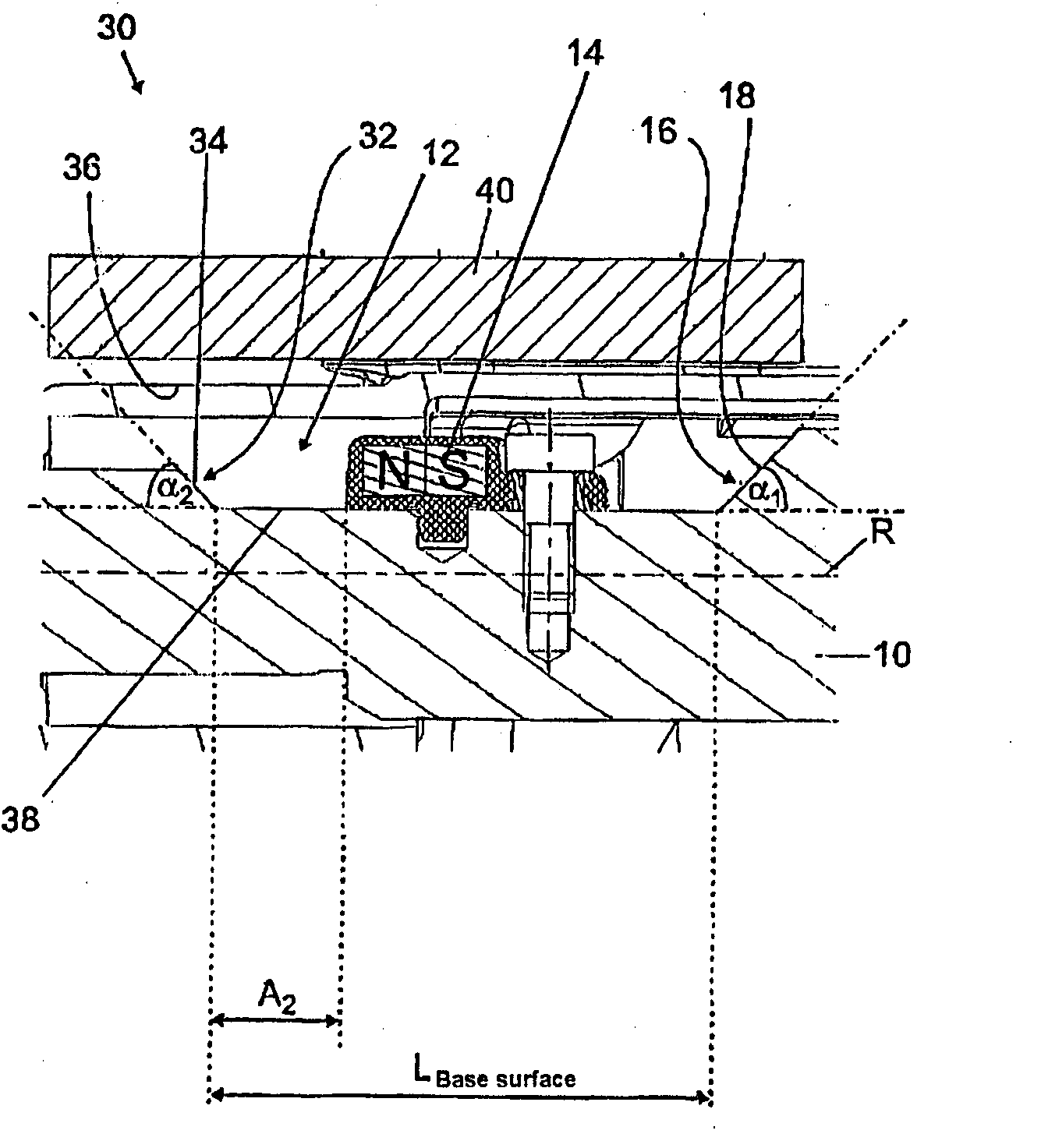
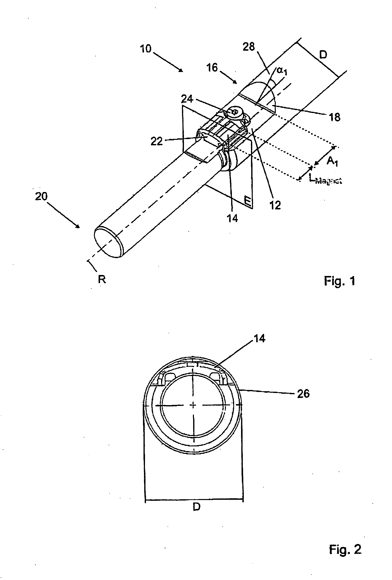
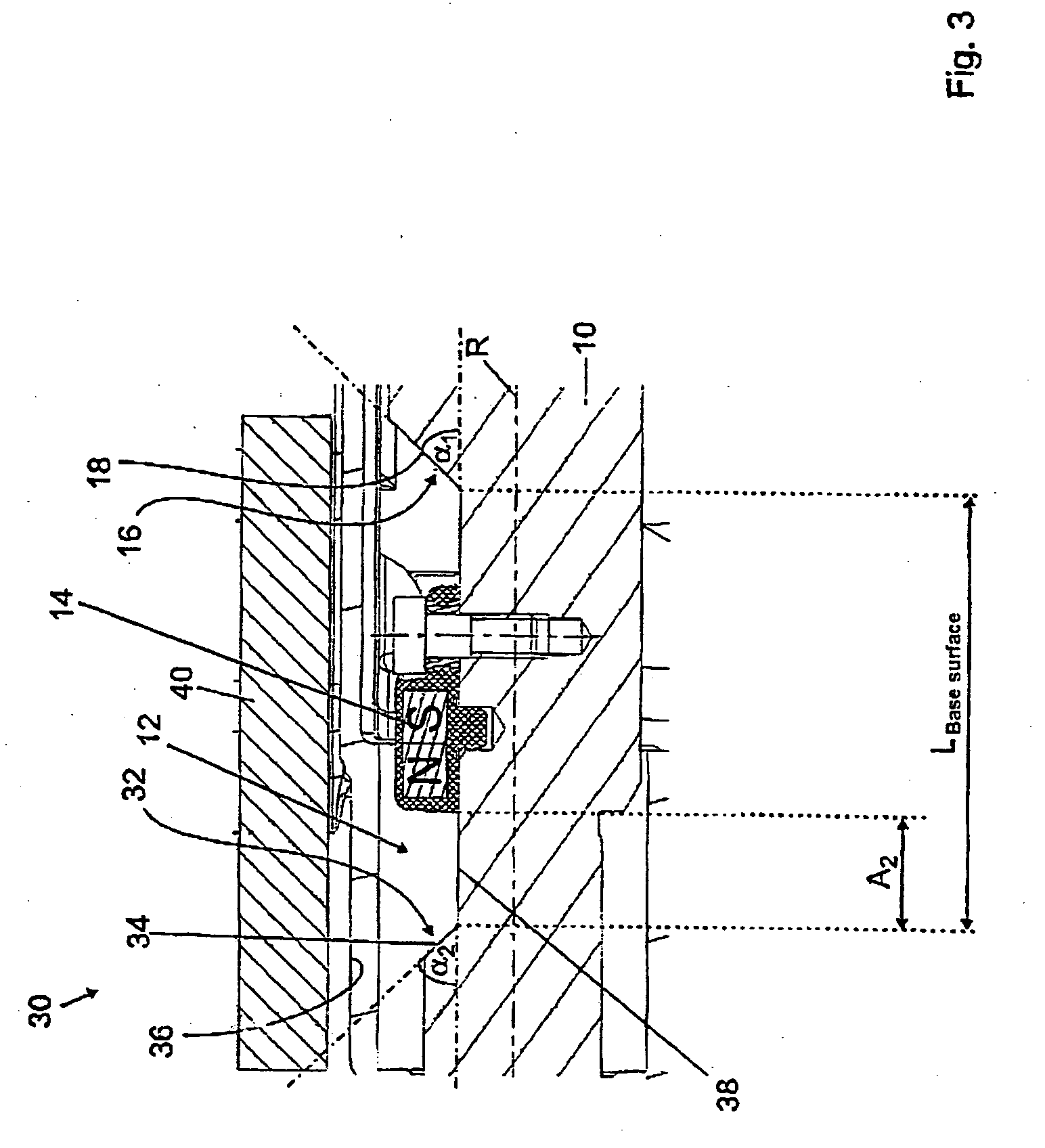
[0029]Referring now to the drawing figures, FIG. 1 shows rod 10 formed from a magnetic material (e.g., steel) having an outside diameter D. Magnet 14 is arranged in cutout 12. The magnet 14 desirably has a field strength of more than 1 tesla—in the present case, for example, the field strength is 1.2 teslas.
[0030]At a first end 16, cutout 12 is delimited by a first cutout wall 18 that constitutes the transition from cutout 12 into rod 10. First cutout wall 18 is inclined relative to a rod longitudinal direction R, and encloses with the latter a first angle α1, which, in the present c...
PUM
 Abstract
Description
Claims
Application Information
 - R&D Engineer
- R&D Manager
- IP Professional
- Industry Leading Data Capabilities
- Powerful AI technology
- Patent DNA Extraction
Browse by: Latest US Patents, China's latest patents, Technical Efficacy Thesaurus, Application Domain, Technology Topic, Popular Technical Reports.
© 2024 PatSnap. All rights reserved.Legal|Privacy policy|Modern Slavery Act Transparency Statement|Sitemap|About US| Contact US: help@patsnap.com