Measuring modal content of multi-moded fibers

a multi-mode fiber and modal content technology, applied in the direction of measurement devices, structural/machine measurement, instruments, etc., can solve the problems of even less useful msup>2 /sup> and potentially confusing

Active Publication Date: 2009-10-22
OFS FITEL LLC
View PDF2 Cites 10 Cited by
  • Summary
  • Abstract
  • Description
  • Claims
  • Application Information

AI Technical Summary

Benefits of technology

[0004]We have developed a technique for analyzing and quantifying the output modal content of optical fibers that support more than one spatial mode. The technique is based on measuring interference between co-propagating modes in the optical fiber. By spatially resolving the interference, an image of the spatial beat pattern between two modes is constructed, thus providing information about the modes that are propagating in the optical fiber.

Problems solved by technology

A problem with applying M2 measurements to optical fibers is that large mode area fibers typically support several modes, and M2 can be relatively insensitive to the amount of power in a higher order mode.
M2 is even less useful, and potentially confusing, when propagation in a higher order mode (HOM) is intentional, as individual HOMs have inherently high values of M2.

Method used


Image

  • Measuring modal content of multi-moded fibers
  • Measuring modal content of multi-moded fibers
  • Measuring modal content of multi-moded fibers

Examples


Embodiment Construction

[0014]In the context intended for this discussion, the subject optical fibers are typically few mode fibers but are referred to here as multi-mode fibers. In typical applications wherein specific modes are characterized, the number of modes propagating in the optical fiber may be few. However, applications may arise where the optical fiber supports many modes but just one, or a few, or even mode groups, may be the subject of the analysis. In some situations, the fiber may be nominally singlemode and a method is desired to analyze the characteristics of weakly guided or weakly radiated higher order modes.

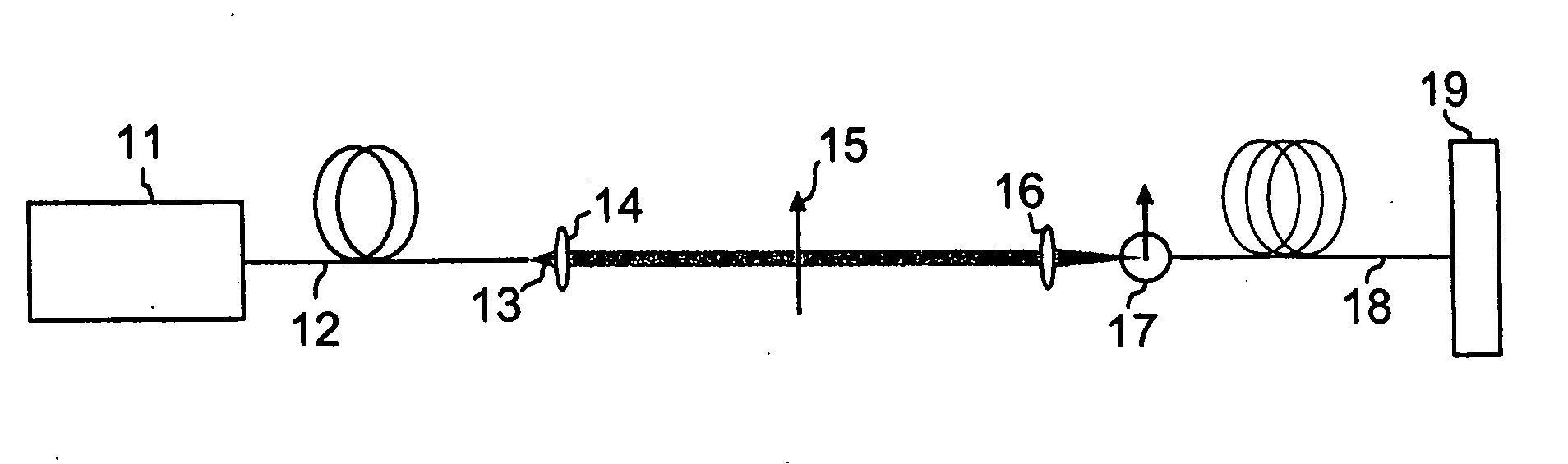
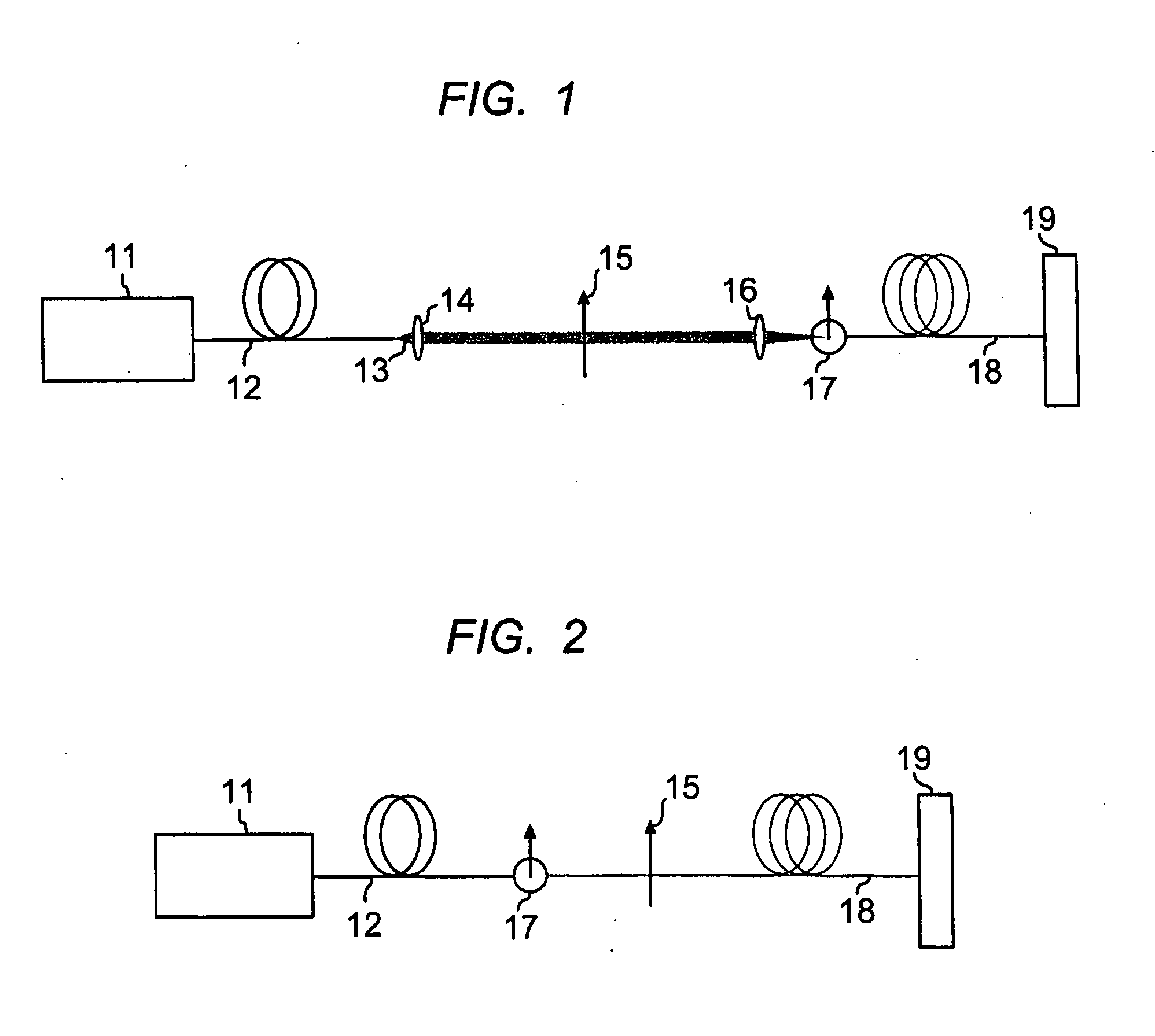
[0015]A schematic of one particular implementation of the measurement technique of the invention is illustrated in FIG. 1. Light from an optical source 11, having a broad bandwidth (few tens of nanometers, or more) such as an amplified spontaneous emission source (ASE), is launched into an optical fiber 12. The optical fiber 12 is the fiber under test and is typically a large-mode-ar...


PUM

PropertyMeasurementUnit
mode-field diameteraaaaaaaaaa
lengthaaaaaaaaaa
lengthaaaaaaaaaa

Abstract

The output modal content of optical fibers that contain more than one spatial mode may be analyzed and quantified by measuring interference between co-propagating modes in the optical fiber. By spatially resolving the interference, an image of the spatial beat pattern between two modes may be constructed, thereby providing information about the modes supported by the optical fiber. Measurements of the phase front exiting the optical fiber under test are advantageously performed in the far field.

Description

RELATED APPLICATION[0001]This application is a Continuation-In-Part of application Ser. No. 12 / 214,629 filed Jun. 20, 2008, claiming the benefit of U.S. Provisional Application No. 61022626, filed Jan. 22, 2008, which applications are incorporated herein by reference.FIELD OF THE INVENTION[0002]This invention relates to analyzing the optical properties of optical waveguides. More specifically it relates to methods and apparatus for measuring mode patterns and power levels in multi-mode optical fibers.BACKGROUND OF THE INVENTION[0003]Optical fiber lasers are desirable for their excellent beam quality, even when operating at high power. The quality of a beam emitted from an optical fiber is frequently quantified using the measure “M2”, which is a measure of how tightly the beam can be focused in free space. A beam with a perfect Gaussian spatial profile has a theoretical M2 value of one. A problem with applying M2 measurements to optical fibers is that large mode area fibers typically...

Claims


Application Information

Patent Timeline
Patent Type & Authority Applications(United States)
IPC IPC(8): G01N21/00
CPCG01M11/331G01N21/412G01M11/335
Inventor NICHOLSON, JEFFREY W.YABLON, ANDREW D.
Owner OFS FITEL LLC
Why Eureka
Try Eureka