
Measuring Equipment for quality of water

a technology for measuring equipment and water quality, applied in the direction of optical radiation measurement, instruments, spectrometry/spectrophotometry/monochromators, etc., can solve the problems of frequent misjudgment, weak substance, and lack of causal relationship between behavior patterns, so as to improve efficiency and accuracy of detecting operation, the effect of raising the reliability of water quality measuremen

Inactive Publication Date: 2009-10-22
BIONEER
View PDF1 Cites 1 Cited by
  • Summary
  • Abstract
  • Description
  • Claims
  • Application Information

AI Technical Summary

Benefits of technology

[0005]An object of the present invention is to provide equipment for measuring water quality that can minimize influences of various internal factors such as health status or other instinct desires of the detector in an operation of bio-monitoring system and thus raise accuracy and reliability of the measurement of the water quality.
[0007]Further object of the present invention is to provide equipment for measuring water quality that can measure efficiently and accurately the water quality using water flea as detector in an efficient operation of a bio-monitoring system.Technical Solution
[0013]In the equipment for measuring water quality according to the present invention, influences of various internal factors such as health status or other instinct desires of the detector is minimized in an operation of a bio-monitoring system and thus reliability of the measurement of the water quality is raised.

Problems solved by technology

However, since the behavior of the detector is influenced by not only environmental factor such as the toxic element, etc. but also various internal factors such as health status or other instinct desires of the detector, a causal relationship between behavior pattern of the detector and measurement of water pollution or harmful substance is not much strong in some cases.
Therefore, misjudgment occurs frequently in the aforementioned prior manner.
Also, it is a challenge to qualitatively analyze sensitivity of the detector according to a range condition of the concentration of the pollutant and a range condition of measuring time.

Method used


Image

  • Measuring Equipment for quality of water
  • Measuring Equipment for quality of water
  • Measuring Equipment for quality of water

Examples


Embodiment Construction

[0020]

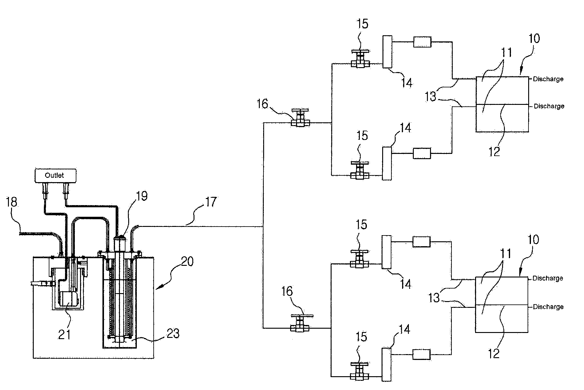
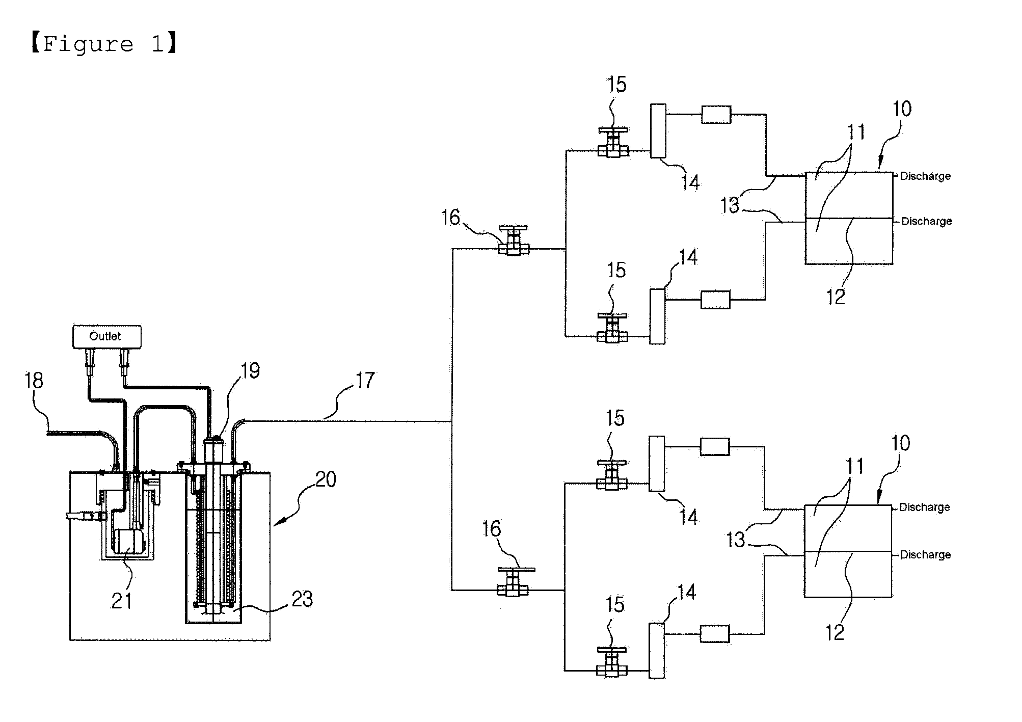
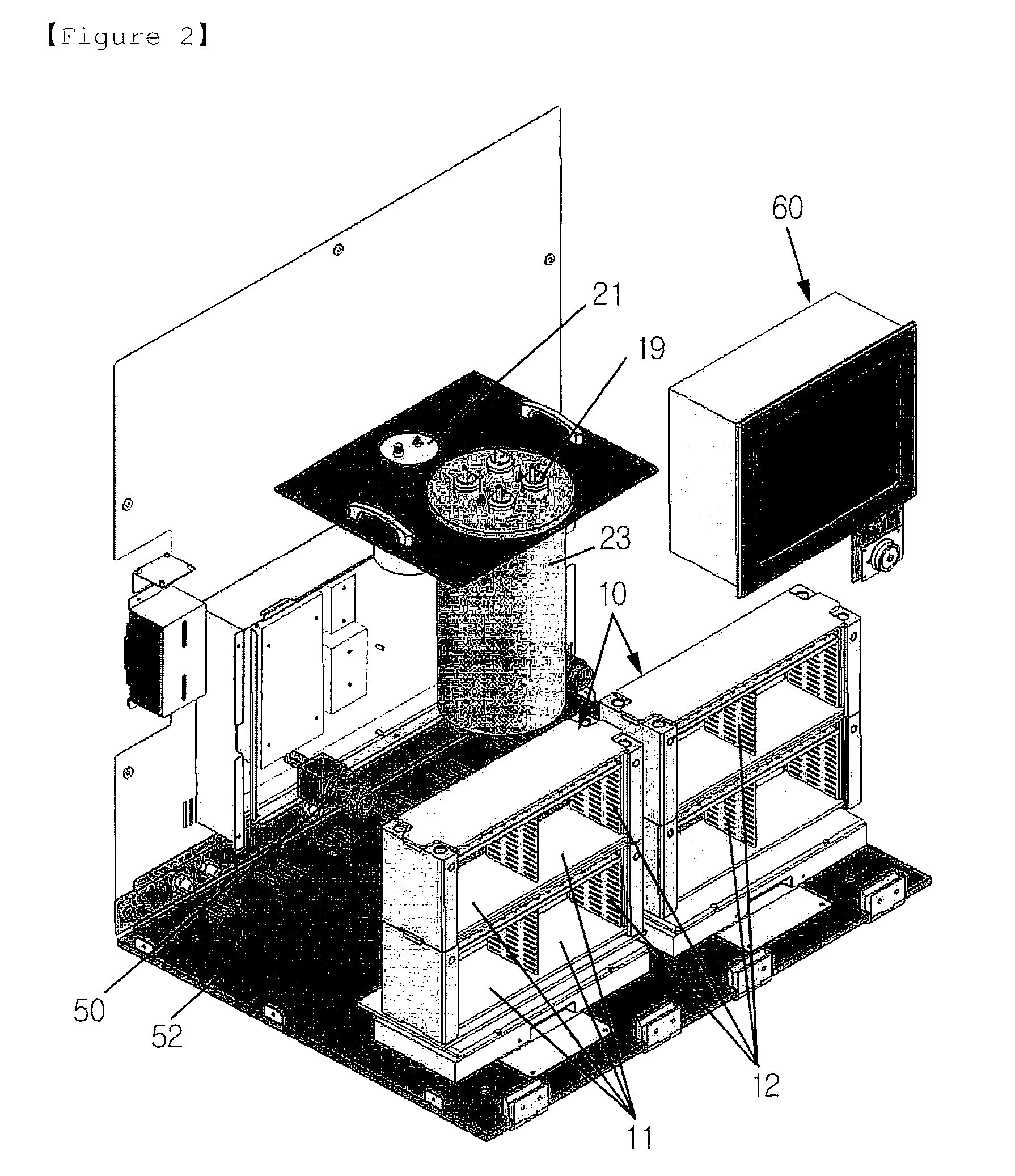
10, 30:test chamber11, 31:containing space12, 32:partition wall13, 17:water supplying passage14, 34:flow gauge15, 16, 36:valve18, 38:water supplying part19, 39:heater20, 40:water supplying unit21, 41:submergible pump23, 43:water tank

Best Mode

[0021]Hereinafter, preferred embodiments of the present invention will be described in detail with reference to accompanying drawings.

[0022]FIG. 1 is a conceptual view illustrating equipment for measuring water quality in a case of using a killifish (or a medaka) as a detector according to an embodiment of the present invention. As shown, there are provided two sets of test chamber 10 and each set has containing spaces 11 to contain a detector therein, the containing spaces 11 being divided into four. A partition wall 12 is formed between the containing spaces 11 of the test chamber 10 and the partition wall 12 is formed with rectangular holes (not shown) having a size smaller than the size of the killifish so that water in the test chambe...


PUM

PropertyMeasurementUnit
temperatureaaaaaaaaaa
distanceaaaaaaaaaa
sizeaaaaaaaaaa

Abstract

The present invention relates to equipment for measuring water quality using a fish or a water flea, an more particularly, to equipment for measuring water quality in which small organisms such as killifish (or medaka) or water flea are put into test chamber having a plurality of divided sections and behavior of the fishes or the water fleas accommodated in the test chamber is observed while continuously flowing water of a river or a water zone to be examined through the test chamber, thereby finding out and measuring existence of toxic element or harmful substance included in the water to be examined.

Description

TECHNICAL FIELD[0001]The present invention relates to equipment for measuring water quality using fish or water flea, more particularly, to equipment for measuring water quality in which small organisms such as killifish (or medaka) or water flea are put into test chamber having a plurality of divided sections and behavior of the fish or the water flea introduced in the test chamber is observed while continuously flowing water of a river or a water zone to be examined through the test chamber, thereby finding out and measuring existence of toxic element or harmful substance included in the water to be examined.BACKGROUND ART[0002]In general, a system for monitoring (monitoring and alarming) using a organisms having an ability of accurately and sensitively responding to specific chemical substance as a detector (test organism) in order to detect toxic element or harmful substance included in water that flows through a river is called as a bio-monitoring system or a early warning syst...

Claims


Application Information

Patent Timeline
Patent Type & Authority Applications(United States)
IPC IPC(8): G01N33/18
CPCG01N33/186
Inventor YOON, SUNG JINKIM, NAM-ILPARK, HAN-OH
Owner BIONEER
Learn More