Duct System For High Power Adapter Cards

a technology of high-power adapter card and duct system, which is applied in the direction of electrical apparatus casing/cabinet/drawer, furniture parts, instruments, etc., can solve the problem that the fan in the chassis cannot be sufficient to deal with the amount of localized nois

Active Publication Date: 2009-10-22
LENOVO GLOBAL TECH INT LTD
View PDF78 Cites 25 Cited by
  • Summary
  • Abstract
  • Description
  • Claims
  • Application Information

AI Technical Summary

Benefits of technology

[0006]One embodiment of the present invention provides an apparatus that substantially prevents recirculation of heated air from an exhaust outlet of an expansion card to an air inlet of the expansion card, wherein the air inlet and exhaust outlet are both on the front end of the chassis. The apparatus comprises a chassis including at least one chassis fan directed to move air in a first direction through the chassis from a front end to a back end, a motherboard disposed within the chassis and having an expansion slot adjacent the front end of the chassis, and an expansion card having an edge connector in communication with the expansion slot and a mounting bracket secured to the front end of the chassis. The expansion card also includes a card fan configured to move cooling air through an air inlet in the front end, move the cooling air across a portion of the expansion card to take on heat, and direct the heated air to an exhaust outlet in the front end. In addition, the apparatus includes an air duct having a first end secured in direct communication with the exhaust outlet, wherein the air duct redirects the heated air toward the back end of the chassis to a second end of the air duct that opens into communication with the at least one chassis fan, wherein the air duct substantially prevents recirculation of the heated air from the exhaust outlet to the air inlet and causes the heated air to exit through the at least one chassis fan.

Problems solved by technology

When a high power expansion card is installed on the motherboard, the chassis fans may not be sufficient to deal with the amount of localized heat-generation caused by operation of the expansion card.

Method used


Image

  • Duct System For High Power Adapter Cards
  • Duct System For High Power Adapter Cards
  • Duct System For High Power Adapter Cards

Examples


Embodiment Construction

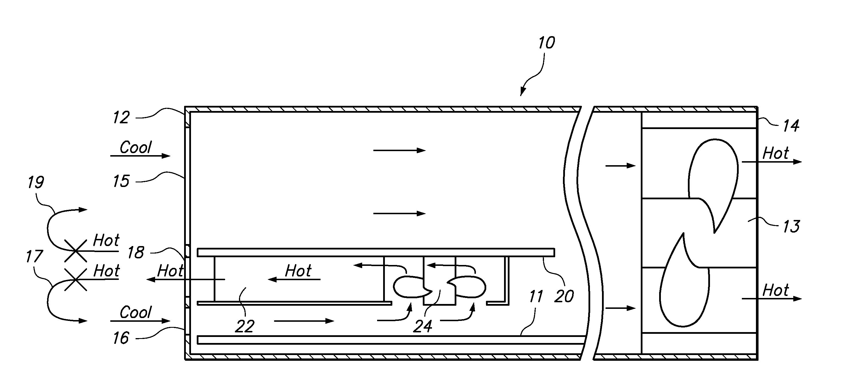
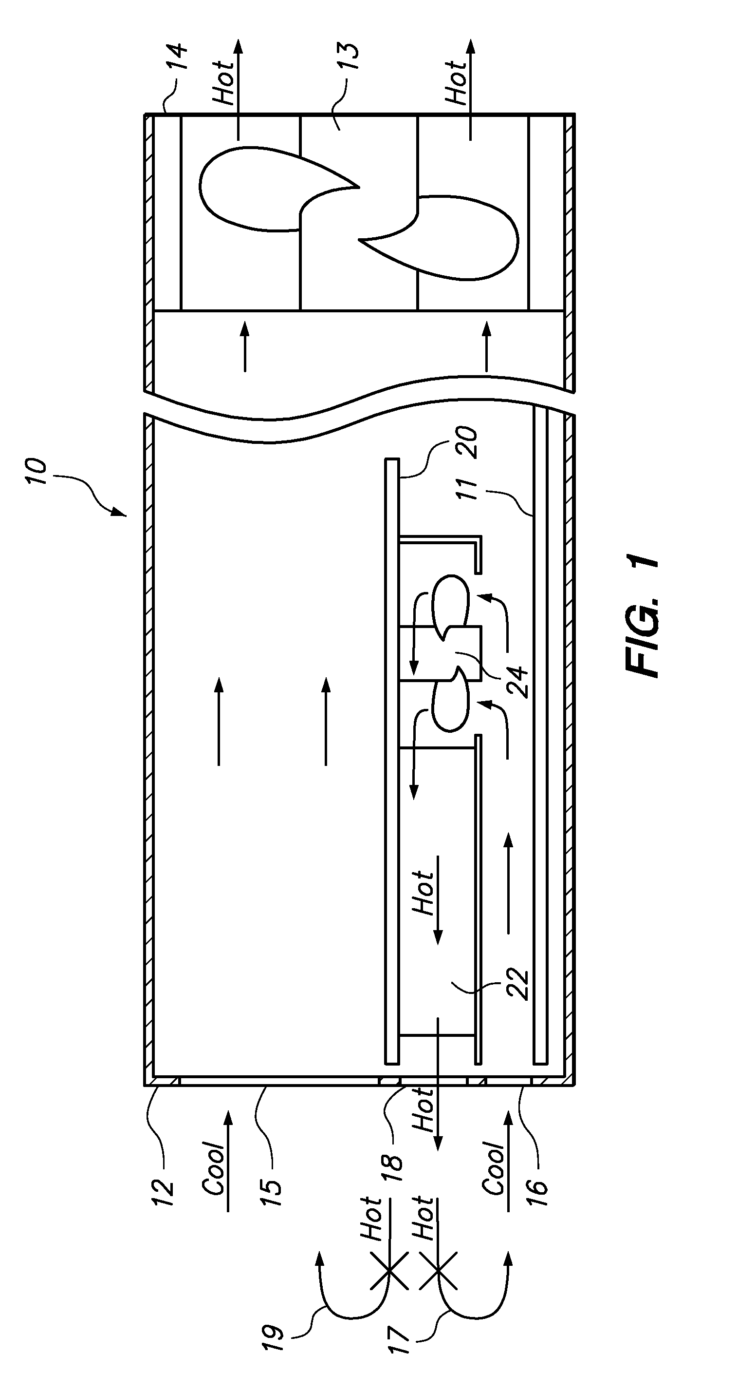
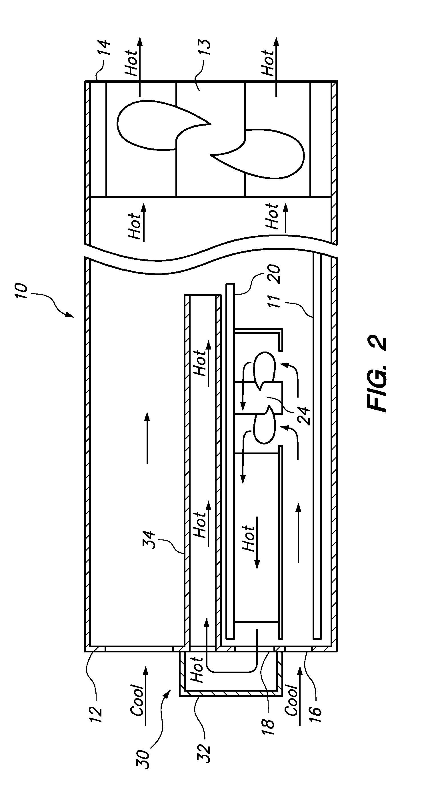
[0013]One embodiment of the present invention provides an apparatus that substantially prevents recirculation of heated air from an exhaust outlet of an expansion card to an air inlet of the expansion card, wherein the air inlet and exhaust outlet are both on the front end of the chassis. The apparatus comprises a chassis including at least one chassis fan directed to move air in a first direction through the chassis from a front end to a back end, a motherboard disposed within the chassis and having an expansion slot adjacent the front end of the chassis, and an expansion card having an edge connector in communication with the expansion slot and a mounting bracket secured to the front end of the chassis. The expansion card also includes a card fan configured to move cooling air through an air inlet in the front end, move the cooling air across a portion of the expansion card to take on heat, and direct the heated air to an exhaust outlet in the front end. In addition, the apparatus...


PUM


Abstract

Method and apparatus for substantially preventing recirculation of heated air from an exhaust outlet of an expansion card to an air inlet of the expansion card, wherein the air inlet and exhaust outlet are both on the same end of the chassis. The apparatus comprises a chassis with a chassis fan, a motherboard within the chassis having an expansion card connector, and an expansion card in communication with the expansion card connector and secured to the front end of the chassis. The expansion card also includes a card fan configured to move cooling air through the air inlet to the exhaust outlet. An air duct redirects the hot air from the exhaust outlet to prevent recirculation into the expansion card and causes the heated air to exit through the chassis fan. The air duct may include a longitudinal segment through a computer module and a lateral segment selectively securable over the exhaust outlet.

Description

BACKGROUND OF THE INVENTION[0001]1. Field of the Invention[0002]The present invention relates to thermal management of computer systems, and more specifically to the movement of air in a computer chassis.[0003]2. Background of the Related Art[0004]Computer systems are generally provided inside a chassis to provide physical support and air circulation for each of the individual components. A typical chassis will include a motherboard, one or more data storage device, a power supply and one or more chassis fan. The motherboard itself may include any number of standard heat-generating components, such as a processor, memory, basic input / output system (BIOS) and interconnecting circuitry. However, a motherboard may also include one or more expansion slots, such as a peripheral component interface (PCI) connector that allows the capability or capacity of the computer system to be expanded.[0005]When a high power expansion card is installed on the motherboard, the chassis fans may not be ...

Claims


Application Information

Patent Timeline
Patent Type & Authority Applications(United States)
IPC IPC(8): G06F1/20
CPCG06F1/20G06F1/185
Inventor BEAUCHAMP, WILLIAM NORRISDITTUS, KARL KLAUSSCOTT, III, WHITCOMB RANDOLPHXU, JEAN JIDONG
Owner LENOVO GLOBAL TECH INT LTD
Why Eureka
Try Eureka