
Intermittent communication system, base station apparatus and mobile station apparatus

Active Publication Date: 2009-10-22
FUJITSU LTD
View PDF32 Cites 13 Cited by
  • Summary
  • Abstract
  • Description
  • Claims
  • Application Information

AI Technical Summary

Benefits of technology

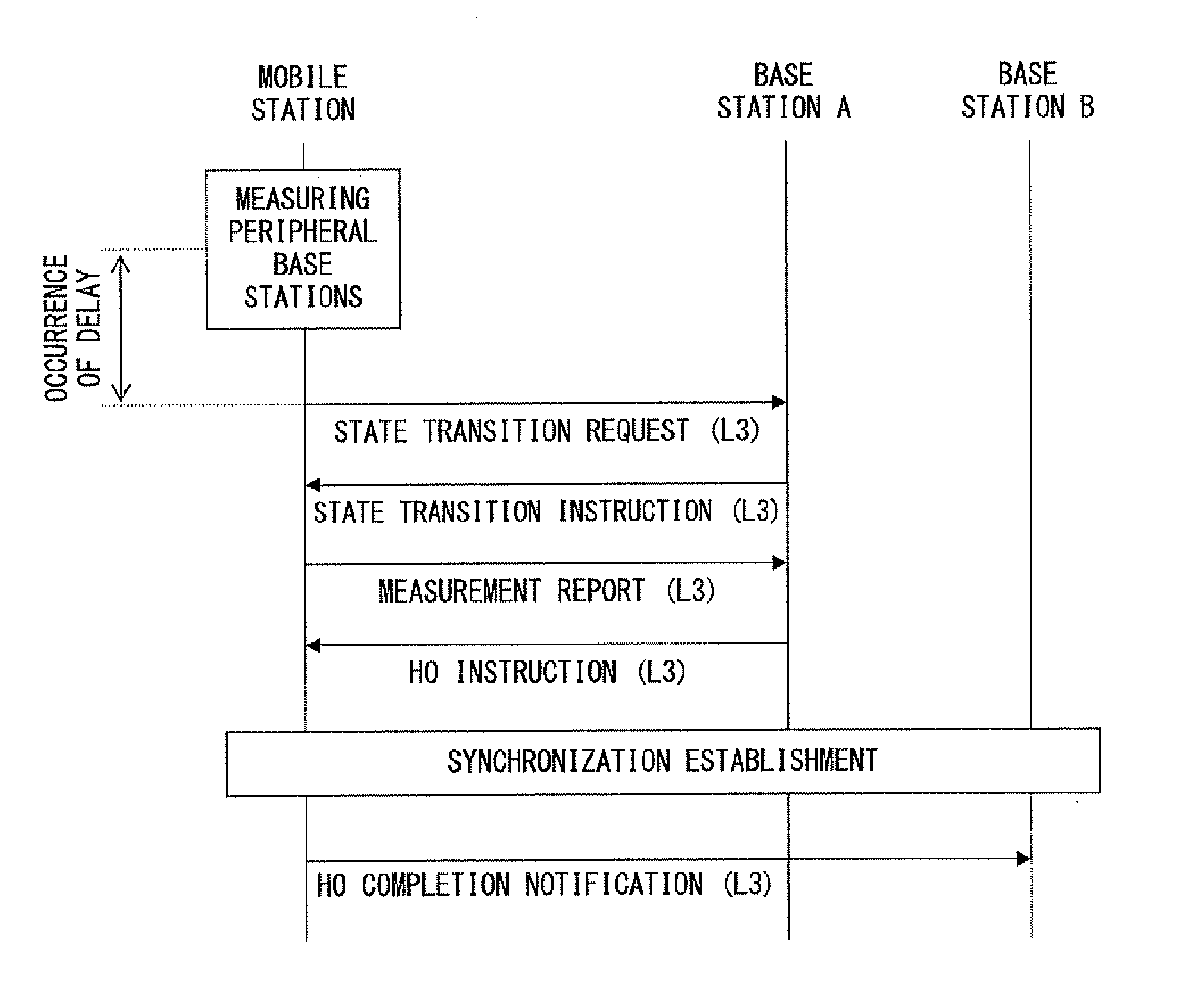
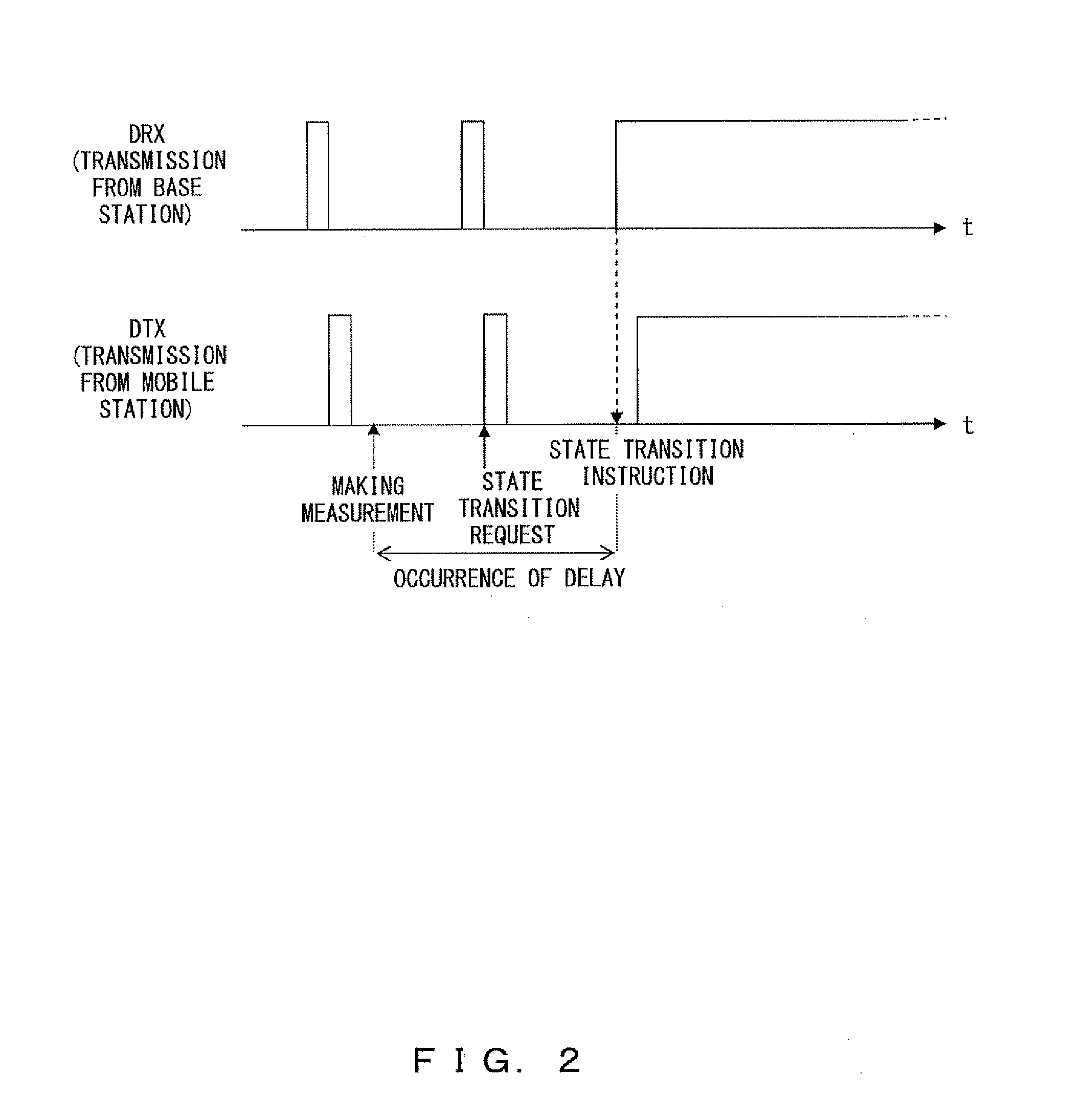
[0015]The mobile station apparatus in the intermittent communication state immediately transmits to the base station apparatus the request to change the communication to the normal communication state without waiting for the next intermittent transmission timing if it determines a handover to be required. Moreover, the mobile station apparatus transmits the request, and at the same time, it transits from the intermittent communication to the normal communication. Upon completion of transiting to the normal communication, a handover is started. Since the request is transmitted to the base station apparatus regardless of intermittent transmission timing, the amount of time required for the handover process can be reduced.
[0019]According to the present invention, a request for the base station apparatus to transit the state regardless of intermittent transmission timing is transmitted by using a common channel even if a handover becomes necessary during an intermittent communication. Since the request is transmitted without waiting for the next intermittent transmission timing, the amount of time required to transit from the intermittent communication state to the normal communication state is reduced. As a result, the amount of time required until the completion of a handover can be shortened. Accordingly, problems such as communication quality degradation, a failure of the handover process, etc., which occur with a prolonged handover process, can be improved.

Problems solved by technology

Additionally, there is a problem such that the handover is not properly performed because it is not complete within a predetermined duration due to a prolonged time required until the transmission of the state transition request.

Method used


Image

  • Intermittent communication system, base station apparatus and mobile station apparatus
  • Intermittent communication system, base station apparatus and mobile station apparatus
  • Intermittent communication system, base station apparatus and mobile station apparatus

Examples


first embodiment

[0040]FIG. 4 illustrates a configuration of the mobile station 2 according to the first embodiment. The mobile station 2 includes an antenna 20, a receiver 21, a peripheral level measuring unit 22, a handover determining unit (denoted as an HO determining unit in FIG. 4) 23, a controlling unit 24, an intermittent transmission / reception period setting unit (DTX / DRX period setting unit in FIG. 4: hereinafter referred to as a period setting unit) 25, a data processing unit 26 and a transmitter 27.

[0041]The antenna 20 is used to transmit a signal to the base station 3, or to receive a signal transmitted from the base station 3. In FIG. 4, the transmission antenna and the reception antenna are collectively represented as one antenna.

[0042]The receiver 21 performs amplification and demodulation processes for a signal received via the antenna 20. The reception level of the demodulated signal is provided to the peripheral level measuring unit 22.

[0043]The peripheral level measuring unit 22 ...

second embodiment

[0080]A wireless communication system 1 according to the second embodiment is characterized in changing from the intermittent communication state to the active state on the basis of information when the information about peripheral base stations is notified as L1 information from the mobile station 2 to the base station 3.

[0081]FIG. 11 illustrates a configuration of the mobile station 2 according to the second embodiment. The mobile station 2 according to this embodiment is different from that according to the above described first embodiment in the point of further including a peripheral base station information managing unit 29. Other constituent elements are similar to those of FIG. 4.

[0082]The peripheral base station information managing unit 28 holds information about peripheral base stations, which is received from a base station 3 at a connection destination. Here, the information about peripheral base stations is identification information for respectively identifying the pe...

third embodiment

[0105]A wireless communication system 1 according to the third embodiment is characterized in performing a handover by setting a method for transmitting to the base station 3 a request to transit a communication state to the active state in accordance with the period of intermittent transmission / reception.

[0106]FIG. 17 illustrates a configuration of the mobile station 2 according to this embodiment. The mobile station 2 according to this embodiment is different from that according to the above described first embodiment in the point that the period setting unit 25 provides the handover determining unit 23 with information about the period of intermittent transmission / reception. Other constituent elements are similar to those of FIG. 4.

[0107]The handover determining unit 23 decides a method for performing a handover, specifically, a method for transmitting the request to transit the communication state to the base station 3 on the basis of the information about the period of intermit...


PUM


Abstract

In an intermittent communication system where an intermittent communication can be made between a base station and a mobile station, a transmitting unit of the mobile station transmits a request to start a normal communication after stopping an intermittent communication at timing different from the intermittent communication if a handover is determined to be required. A transiting unit transits from the intermittent communication to the normal communication after the transmitting unit transmits the request. A handover performing unit performs a handover upon completion of transition to the normal communication by the transiting unit.

Description

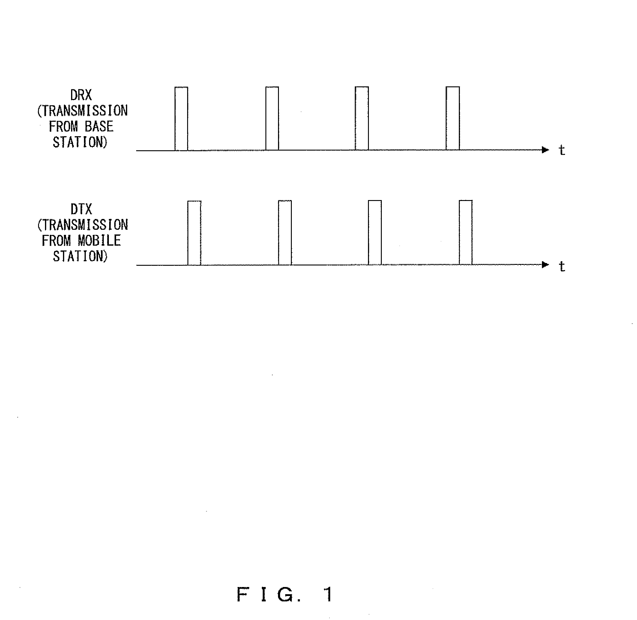
CROSS-REFERENCE TO RELATED APPLICATION[0001]This application is based upon and claims the benefit of priority of the prior PCT Application No. PCT / JP2007 / 050878, filed on Jan. 22, 2007, the entire contents of which are incorporated herein by reference.FIELD[0002]The present invention relates to a handover technique in a mobile communication system where an intermittent communication can be made.BACKGROUND[0003]In mobile communication systems such as a cellular phone, etc., third-generation CDMA (Code Division Multiple Access) systems are currently providing various types of services. Mobile communication systems of the next generation or later, which enable a faster communication, are currently under study. LTE (Long Term Evolution) is currently under study in 3GPP (3rd Generation Partnership Project). For example, in LTE, a method by which a mobile station applies intermittent reception (DRX: discontinuous reception) during not only a standby state but also a communication state. T...

Claims


Application Information

Patent Timeline
IPC IPC(8): H04W36/00H04W76/04
CPCH04W36/00H04W52/0209H04W76/048H04W76/046H04W76/27H04W76/28Y02D30/70H04W36/08H04W36/0016H04W36/30H04W74/0833
Inventor TAJIMA, YOSHIHARUOBUCHI, KAZUHISATANAKA, YOSHINORIKAWASAKI, YOSHIHIROOHTA, YOSHIAKISUGIYAMA, KATSUMASA
Owner FUJITSU LTD
Learn More