Femoral component of an artificial knee joint

Inactive Publication Date: 2009-10-22
MANDELL STEVEN L
View PDF21 Cites 98 Cited by
  • Summary
  • Abstract
  • Description
  • Claims
  • Application Information

AI Technical Summary

Benefits of technology

[0028]Another object of the present invention is to provide an artificial knee joint which provides a greater amount of contact between condyles and increase flexion within the artificial knee joint.
[0029]Another object of the present invention is to provide an artificial knee joint which includes a set of femoral components of different sizes for different sized femurs, with each of the components in the set having many surfaces which share

Problems solved by technology

While the human knee joint is capable of supporting most of these typical loads under normal conditions for the life of the individual, in certain circumstances the human knee joint suffers degraded performance.
For instance, artificial knee joints are known for being somewhat complex to implant, and most particularly the femoral component.
Such extensive inventory of cutting jigs is expensive to maintain, requires additional space within the surgery room or nearby, and presents the greater possibility of problems during or after surgery.
Furthermore, an increase of such cutting jigs is more difficult to clean and sterilize which increases the potential for infection, in turn resulting in a less than fully desirable outcome.
U.S. Pat. Nos. 5,925,049 and 5,749,876 both describe a femoral cutting instrument sizer that allows a single tool to be used for a set of femoral components of different sizes however both devices are cumbersome and comp

Method used


Image

  • Femoral component of an artificial knee joint
  • Femoral component of an artificial knee joint
  • Femoral component of an artificial knee joint

Examples


Embodiment Construction

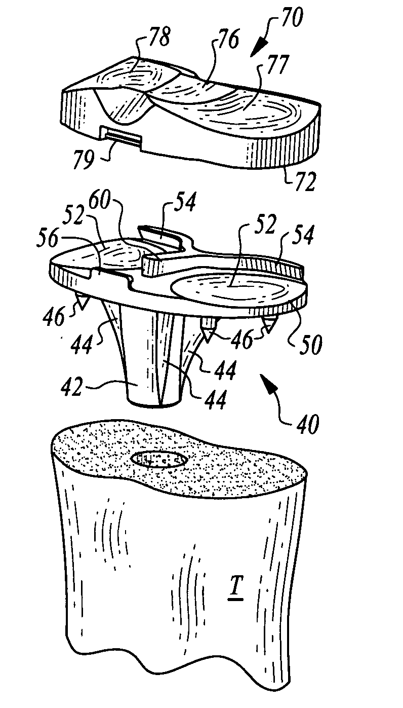
[0061]Referring to the drawings, wherein like reference numerals represent like parts throughout the various drawing figures, reference numeral 10 is directed to an artificial knee joint for replacing a natural knee joint between a femur F and a tibia T. The invention includes a femoral component 20 and a tibial component 40, as well as tools 2, 12 for forming a distal end of the femur F to receive the femoral component 20. The invention also includes methods for preparing the distal end of the femur to receive an appropriately sized femoral component.

[0062]In essence, and with particular reference to FIGS. 15 and 16, the basic details of the artificial knee joint 10 are described, according to a preferred embodiment. The joint 10 includes the femoral component 20 adapted to be coupled to an appropriately shaped distal end of the femur F. The joint 10 also includes a tibial component 40. The tibial component 40 primarily includes a shaft 42 for insertion into the proximal end of the...


PUM


Abstract

A femoral component of an artificial knee joint is configured with multiple different facets which are similar in size and shape for many different sizes, to simplify an associated method for forming a distal end of the femur to receive the femoral component. Jig embodiments are provided to form surfaces on a distal end of a femur to correspond with facets of the femoral component, with the same jig usable for femoral components of differing size. The femoral component includes medial and lateral condylar legs with a posterior facet of the femoral component exhibiting a negative angle relative to a central axis of the femur, to maximize contact and increase flexion of the artificial knee joint.

Description

CROSS-REFERENCE TO RELATED APPLICATIONS[0001]The following patent application is being filed in coordination with another patent application having a very similar disclosure and related to other portions of a common artificial knee joint. This other corresponding application is entitled “TIBIAL COMPONENT OF AN ARTIFICIAL KNEE JOINT,” has the same inventor, was filed on the same day and has Docket No. 07112.101.FIELD OF THE INVENTION[0002]The following invention relates to surgical implants placed within a knee of a patient to function as an artificial knee joint. More particularly, this invention relates to artificial knee joints which include a femoral component, a tibial component and a patellar component which exhibit a simplified femoral component, femoral component sizing, bone preparation procedures, tibial component meniscal insert low wear characteristics and dual direction knee pivoting rotation function therein.BACKGROUND OF THE INVENTION[0003]Human knee joints endure exce...

Claims


Application Information

Patent Timeline
IPC IPC(8): A61F2/38A61B17/58
CPCA61B17/155A61F2250/0018A61F2/38A61F2/389A61F2002/30014A61F2002/30245A61F2002/30354A61F2002/30378A61F2002/30387A61F2002/30428A61F2002/30438A61F2002/30563A61F2002/30616A61F2002/30841A61F2002/3085A61F2002/30878A61F2220/0025A61F2220/0033A61F2220/0041A61F2230/0071A61F2/30734A61F2002/30433
Inventor MANDELL, STEVEN L.
Owner MANDELL STEVEN L
Why Eureka
Try Eureka