
System and Method for Providing Voltage Regulation in a Power Distribution System

Inactive Publication Date: 2009-10-22
S&C ELECTRIC
View PDF20 Cites 277 Cited by
  • Summary
  • Abstract
  • Description
  • Claims
  • Application Information

AI Technical Summary

Benefits of technology

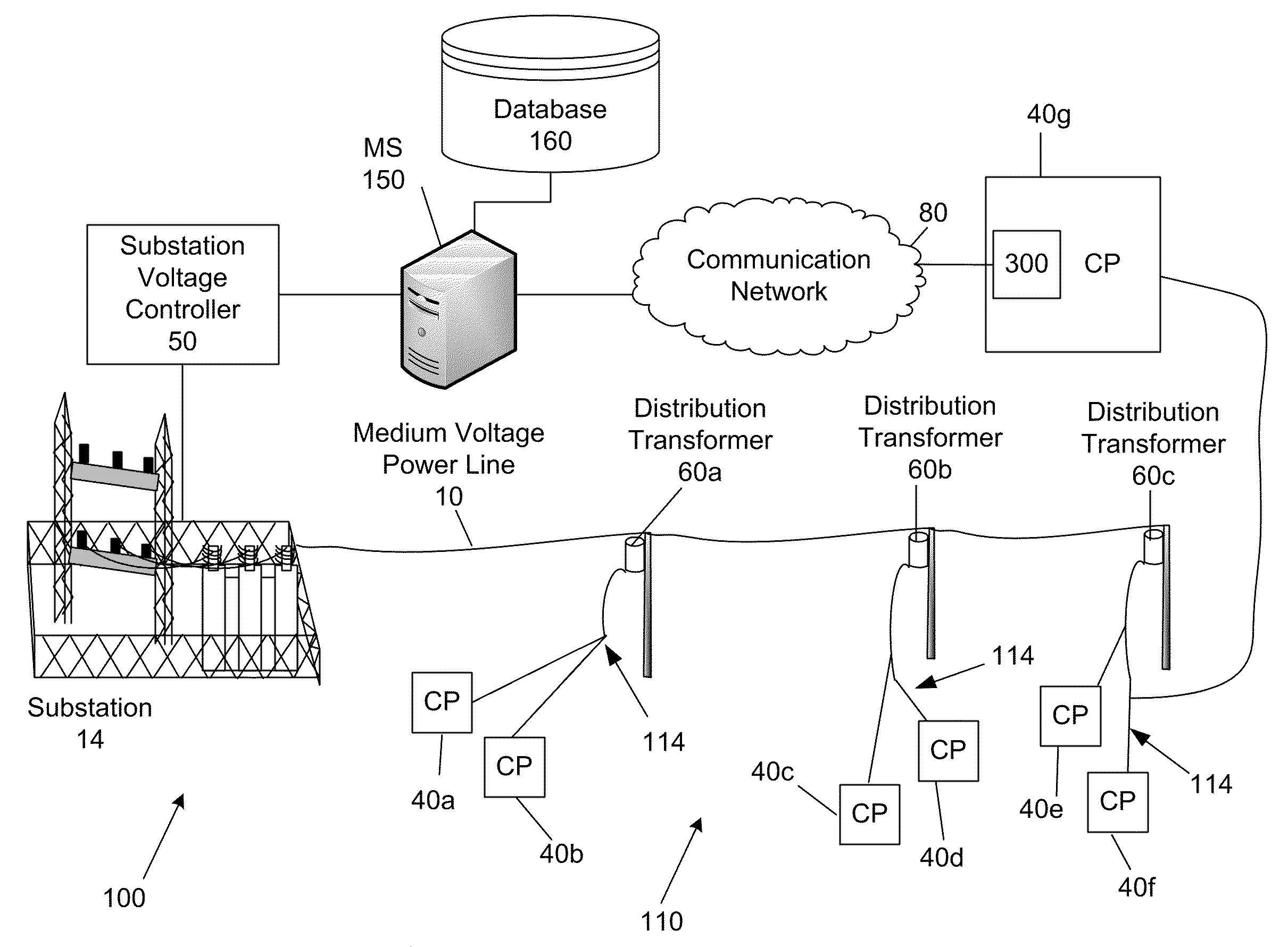
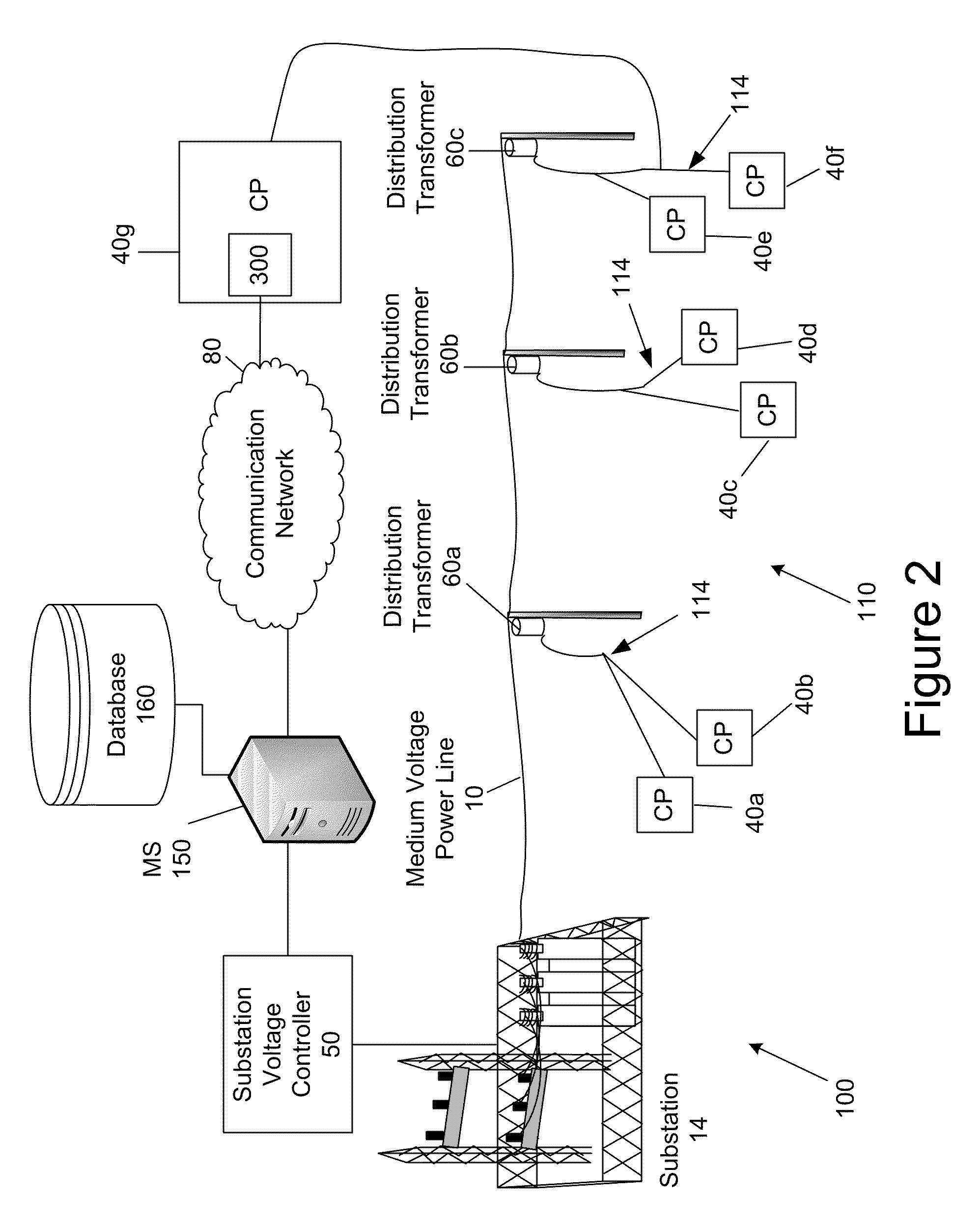
[0007]The present invention provides a system and method of regulating the voltage of the power supplied to a plurality of power customers via a power distribution system that includes low voltage power lines and medium voltage power lines. In one embodiment, the method includes measuring the voltage of a plurality of low voltage power lines at a plurality locations in the power distribution system with a plurality of voltage monitoring devices; with the plurality of voltage monitoring devices, transmitting vol

Problems solved by technology

The economic and environmental cost of generating and distributing power to power customers is enormous.
In addition, an engineering margin must be added to the estimated voltage to be delivered to the power customers due to the uncertainty of the losses of various components of the power grid 100 such as, for example, transformer losses and power line losses.
Regulating a voltage based on an educated “guess” and a margin of error often results in the utility providing a voltage that is higher than required by regulatory requirements, which in some instances causes a greater than necessary delivery of power.
Currently, there is no cost efficient means for an electric utility to accurately determine the precise voltage to be supplied by a substation 14 to provide a desired voltage at a customer premises.

Method used


Image

  • System and Method for Providing Voltage Regulation in a Power Distribution System
  • System and Method for Providing Voltage Regulation in a Power Distribution System
  • System and Method for Providing Voltage Regulation in a Power Distribution System

Examples


Embodiment Construction

[0020]In the following description, for purposes of explanation and not limitation, specific details are set forth, such as particular networks, communication systems, computers, terminals, devices, components, techniques, data and network protocols, software products and systems, operating systems, development interfaces, hardware, etc. in order to provide a thorough understanding of the present invention.

[0021]However, it will be apparent to one skilled in the art that the present invention may be practiced in other embodiments that depart from these specific details. Detailed descriptions of well-known networks, communication systems, computers, terminals, devices, components, techniques, data and network protocols, software products and systems, operating systems, development interfaces, and hardware are omitted so as not to obscure the description.

[0022]In accordance with the principles disclosed herein, a system for performing Conservation Voltage Reduction (CVR)—or otherwise ...


PUM


Abstract

A system and method of regulating the voltage of the power supplied to a plurality of power customers via a power distribution system that includes low voltage power lines and medium voltage power lines is provided. In one embodiment, the method includes measuring the voltage of a plurality of low voltage power lines at a plurality locations in the power distribution system with a plurality of voltage monitoring devices; with the plurality of voltage monitoring devices, transmitting voltage data in real time to a remote computer system; receiving, with the computer system, the real time voltage data of the voltage measured from the voltage monitoring devices; comparing, with the computer system, the real time voltage data with a first threshold value; and if the real time voltage data is beyond the first threshold value, transmitting with the computer system a first voltage adjustment instruction to a voltage control device configured to adjust the voltage supplied to a low voltage power line.

Description

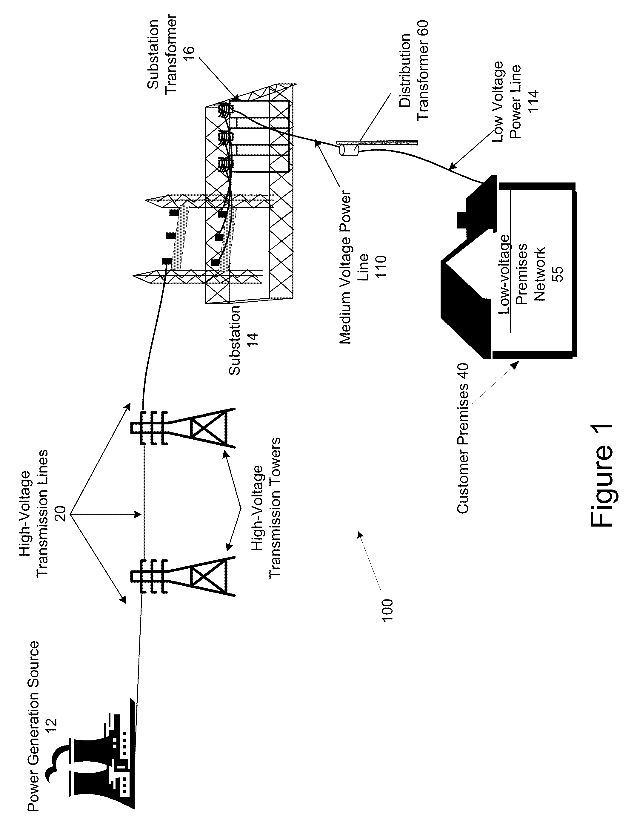
CROSS REFERENCE TO RELATED APPLICATIONS[0001]This application claims priority to U.S. Patent Application No. 61 / 045,851, filed Apr. 17, 2008, which is hereby incorporated herein by reference in its entirety for all purposes.FIELD OF THE INVENTION[0002]The present invention generally relates to the operating a power distribution system and more particularly, to a system and method for operating a power distribution system to regulate the voltage supplied to a plurality of customer premises by the power distribution system.BACKGROUND OF THE INVENTION[0003]The economic and environmental cost of generating and distributing power to power customers is enormous. Even a small percentage reduction in power consumption translates to an enormous financial savings and reduced emissions.[0004]FIG. 1 illustrates a conventional power grid 100. Power is conducted from the substation 14 to one or more distribution transformers 60 over one or more medium voltage (MV) power lines 20. Power is conduct...

Claims


Application Information

Patent Timeline
IPC IPC(8): G06F1/26H02J3/00
CPCH02J3/12H02J3/1878H04Q2209/25Y02E40/30H04Q9/00
Inventor MOLLENKOPF, JAMES D.DEAVER, SR., BRIAN J.HERRON, JR., JOSEPH B.KREISS, DAVID G.
Owner S&C ELECTRIC
Learn More