Multi-tube, can-annular pulse detonation combustor based engine with tangentially and longitudinally angled pulse detonation combustors

a combustor and pulse detonation technology, applied in the field of pulse detonation systems, can solve the problems of relatively large pdcs, difficult to add length, and high pressure peaks and oscillations of pdcs operation

Inactive Publication Date: 2009-10-29
GENERAL ELECTRIC CO
View PDF15 Cites 29 Cited by
  • Summary
  • Abstract
  • Description
  • Claims
  • Application Information

AI Technical Summary

Benefits of technology

[0011]As used herein, a “pulse detonation combustor” PDC (also including PDEs) is understood to mean any device or system that produces both a pressure rise and velocity increase from a series of repeating detonations or quasi-detonations within the device. A “quasi-detonation” is a supersonic turbulent combustion process that produces a pressure rise and velocity increase higher than the pressure rise and velocity increase produced by a deflagration wave. Embodi

Problems solved by technology

However, because of the forces and stresses involved, relatively large PDCs can be impractical.
In many engine applications, this added length is problematic.
Additionally, it is known that the operation of PDCs creates extremely high pressure peaks and oscillations both within the PDC and upstream components, as well as generating high heat within the PDC tubes and surrounding components.
Because of these high temperatures and pressure peaks and oscillations during PDC operation, it is difficult to develop operational systems which can susta

Method used


Image

  • Multi-tube, can-annular pulse detonation combustor based engine with tangentially and longitudinally angled pulse detonation combustors
  • Multi-tube, can-annular pulse detonation combustor based engine with tangentially and longitudinally angled pulse detonation combustors
  • Multi-tube, can-annular pulse detonation combustor based engine with tangentially and longitudinally angled pulse detonation combustors

Examples


Embodiment Construction

[0020]The present invention will be explained in further detail by making reference to the accompanying drawings, which do not limit the scope of the invention in any way.

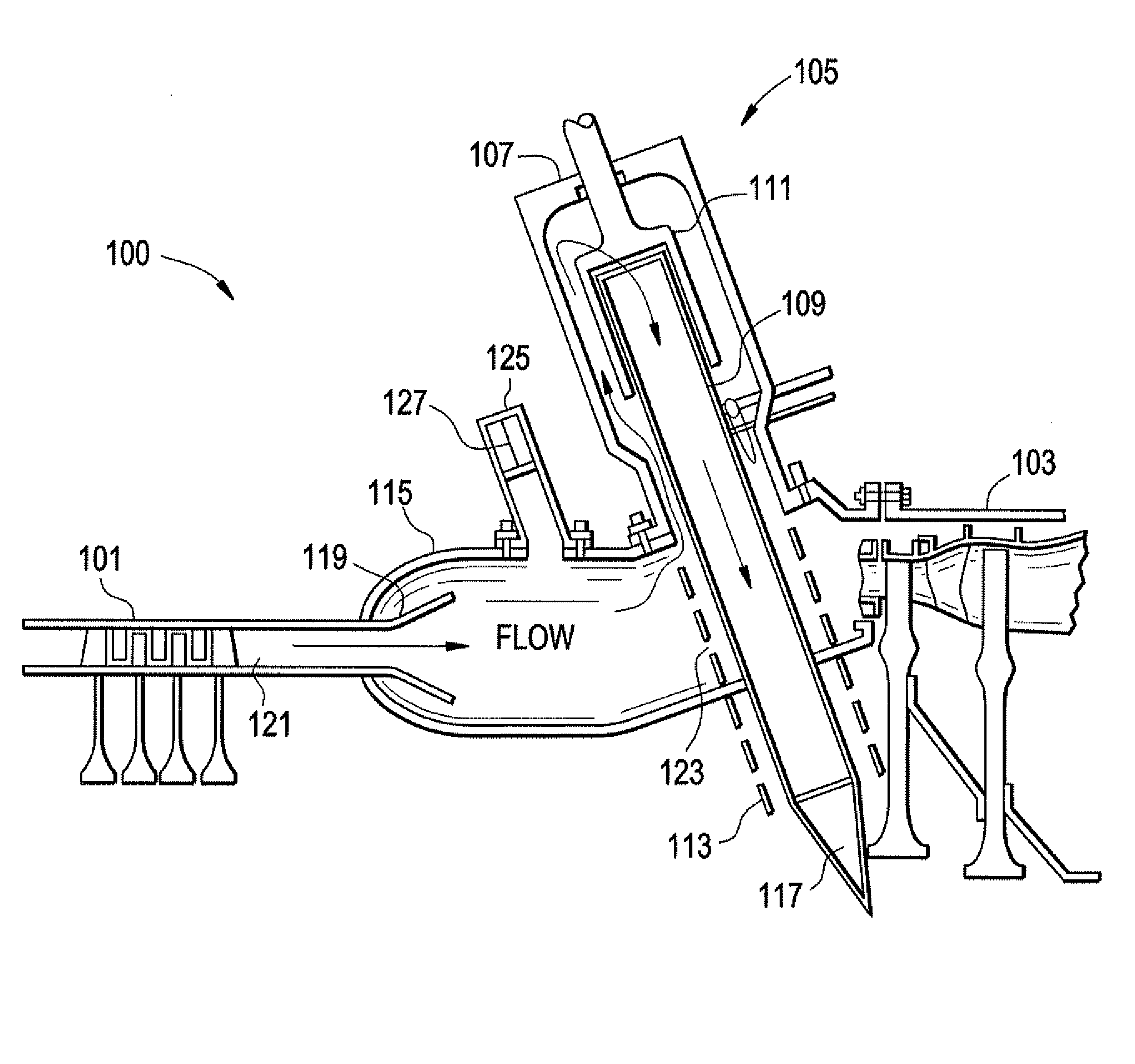
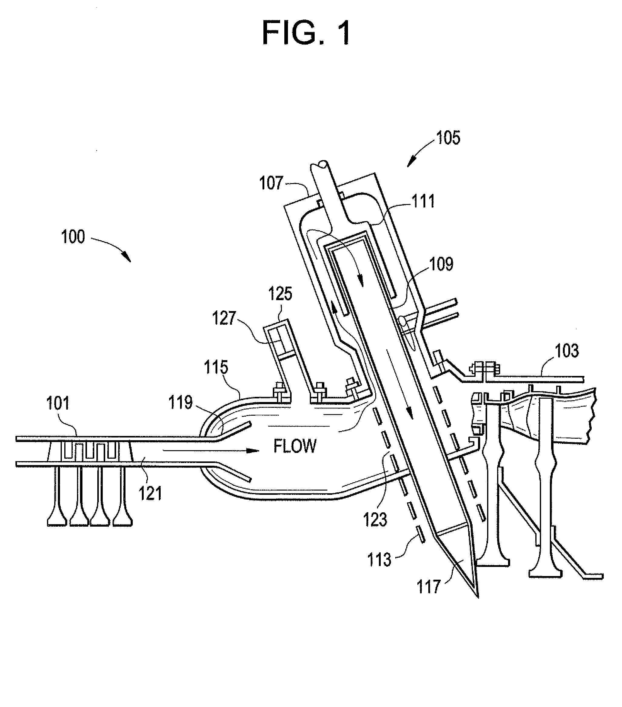
[0021]FIG. 1 depicts a portion of an engine 100 in accordance with an embodiment of the present invention. As shown, the engine 100 contains a compressor stage 101 and a turbine stage 103. These stages are configured in any known or conventional way. Positioned downstream of the compressor stage 101 and upstream of the turbine stage 103 is a PDC stage 105. In the exemplary embodiment shown, the PDC stage 105 fully replaces a conventional combustor stage, such that the PDC stage 105 fully provides the energy normally supplied by the combustion stage. However, the present invention is not limited in this regard. Specifically, it is also contemplated that the PDC stage 105 of the present invention is employed with a combustion stage within the engine 105. This would be similar to a hybrid PDC engine type in which a de...


PUM


Abstract

An engine contains a compressor stage, a pulse detonation combustion stage and a turbine stage. The pulse detonation combustion stage contains at least one pulse detonation combustor which has an inlet portion. The pulse detonation combustor is oriented longitudinally and/or tangentially with respect to a centerline of the engine.

Description

PRIORITY[0001]This invention claims priority to U.S. Provisional Application 60 / 988,171 filed on Nov. 15, 2007, the entire disclosure of which is incorporated herein by reference.BACKGROUND OF THE INVENTION[0002]This invention relates to pulse detonation systems, and more particularly, to a multi-tube, can-annular pulse detonation combustor based engine.[0003]With the recent development of pulse detonation combustors (PDCs) and engines (PDEs), various efforts have been underway to use PDC / Es in practical applications, such as in aircraft engines and / or as means to generate additional thrust / propulsion. Further, there are efforts to employ PDC / E devices into “hybrid” type engines which use a combination of both conventional gas turbine engine technology and PDC / E technology in an effort to maximize operational efficiency. It is for either of these applications that the following discussion will be directed. It is noted that the following discussion will be directed to “pulse detonati...

Claims


Application Information

Patent Timeline
IPC IPC(8): F02C5/02
CPCF02C5/02F02C5/12F23C15/00F05D2250/322F23R3/425F23R7/00F23R2900/00014F23D14/42
Inventor KENYON, ROSS HARTLEYJOSHI, NARENDRA DIGAMBERTANGIRALA, VENKAT ESWARLUDEAN, ANTHONY JOHNRASHEED, ADAMGLASER, AARON JEROME
Owner GENERAL ELECTRIC CO
Why Eureka
Try Eureka