Device and method for monitoring the vibratory condition of a rotating machine

a technology of rotating machines and vibratory conditions, which is applied in the direction of rotary bearings, static/dynamic balance measurement, level indicators, etc., can solve the problems of mechanical components that are not able to meet the needs of use, deterioration of rolling parts such as rings, and fatigue, etc., to achieve low cost, low loss, and free of damping

Active Publication Date: 2009-10-29
UNIV DE REIMS CHAMPAGNE ARDENNE
View PDF9 Cites 16 Cited by
  • Summary
  • Abstract
  • Description
  • Claims
  • Application Information

AI Technical Summary

Benefits of technology

[0020]One advantage of the invention is that the capacitive sensor formed by the pair of capacitor plates can be placed inside the bearing, that is to say at the optimum position in which all of the vibration information transits, so that it is free of any damping.
[0021]Another advantage of the invention is that these sensors are positioned as close as possible to the parts in movement, allowing one to obtain a signal of high quality with little loss.
[0022]Another advantage of the invention is that these capacitive sensors provide access firstly to the radial forces and secondly to the axial forces of the bearings.
[0023]Another advantage of the device of the invention is characterised by its small size which enables it to be incorporated directly into the machine.
[0024]Another advantage contributed by the invention is the low cost of its implementation. This allows the invention to be used systematically during the design at the industrial leve...

Problems solved by technology

And yet, although the use of bearings reduces the friction effects due to the rotation of a shaft in its bearing assembly, fatigue in the mechanical components will appear once a certain number of rotations has been exceeded.
This deterioration reaches the rolling parts such as the rings.
The deterioration can take the form of normal wear, surface chipping, corrosion, seizing, abrasion, etc., which then generates an impact, or can take the form of an unbalance in the shaft causing a dynamic lack of balance.
This deterioration in the condition of the mechanism then leads to vibration, which increases with the wear.
Unbalance conditions from an unbalance in the shaft produces a sinusoidal excitation while surface chipping on a track in a bearing brings about a shock wave that leads to...

Method used


Image

  • Device and method for monitoring the vibratory condition of a rotating machine
  • Device and method for monitoring the vibratory condition of a rotating machine
  • Device and method for monitoring the vibratory condition of a rotating machine

Examples


Embodiment Construction

[0061]The present invention will now be described more fully hereinafter with reference to the accompanying drawings, in which a preferred embodiment of the invention is shown. This invention may, however, be embodied in many different forms and should not be construed as limited to the embodiments set forth herein. Rather, these embodiments are provided so that this disclosure will be thorough and complete, and will fully convey the scope of the invention to those skilled in the art. Like numbers refer to like elements throughout.

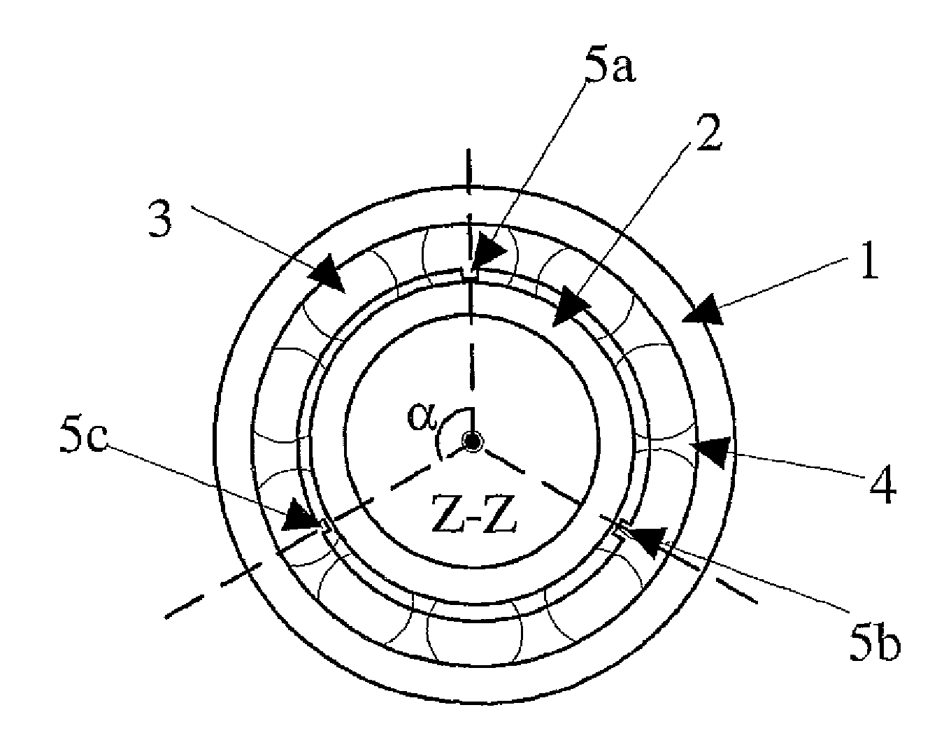
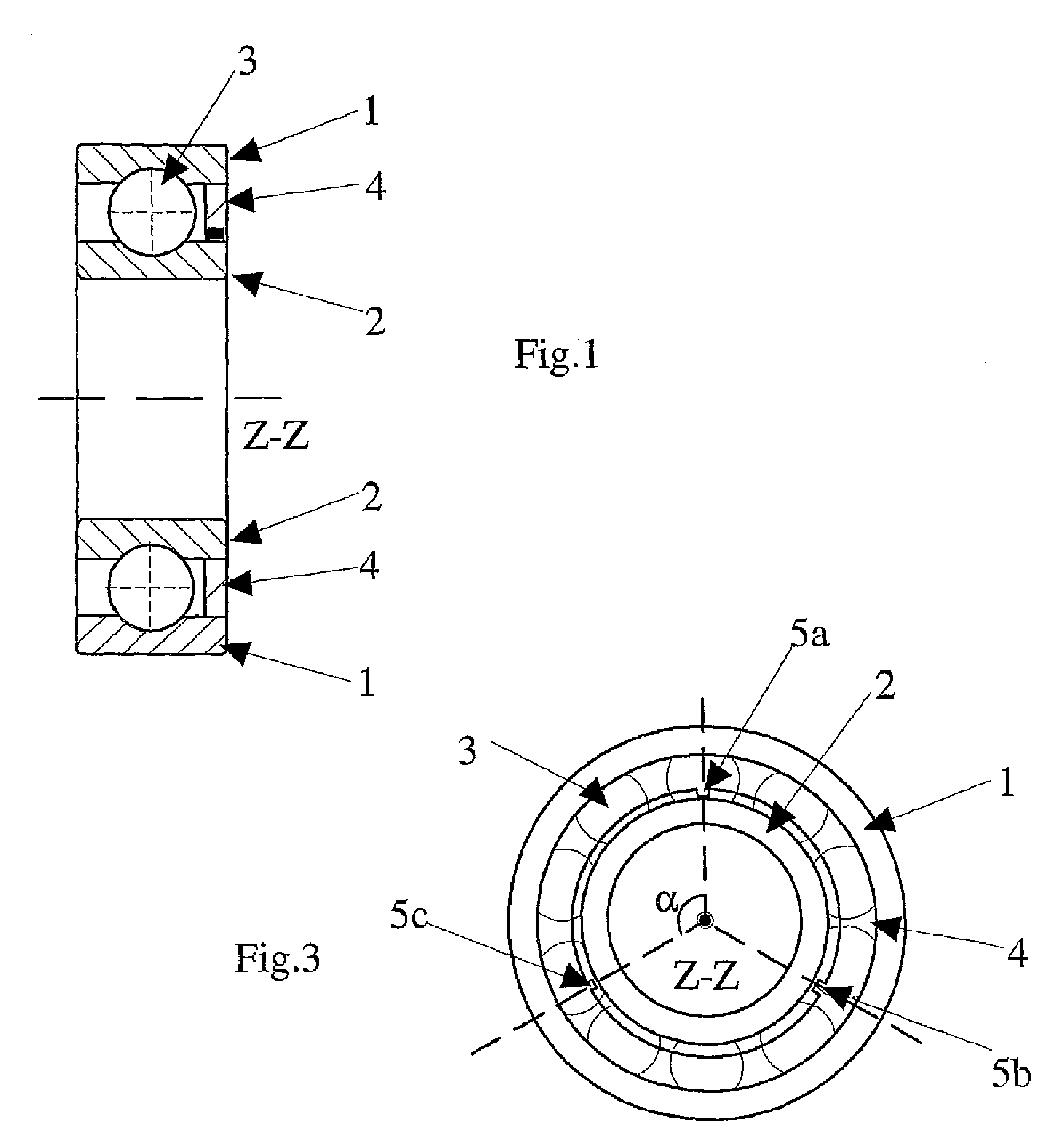
[0062]The mechanical bearing is formed from two coaxial rings, one inner (2) and the other outer (1,) between which rolling elements (3) are placed and held trapped. Stated differently, the rolling elements are movably positioned, or capable of moving, between the outer and inner ring. These various parts are generally made of steel in order to be resistant to compression. The inside face of the outer ring (1), as well as the outside face of the inner ring...


PUM


Abstract

This present invention concerns a device having a mechanical bearing formed by two coaxial rings, one fixed relative to the machine and the other rotating, between which at least one rolling element is moveably positioned, at least one non-conducting positioning means secured to the fixed bearing ring, the positioning means including at least one placement holder for at least one conducting element forming a first plate of a capacitor, at a distance from a conducting part of the rotating ring forming the second plate of the capacitor, and with the positioning means attached to at least one partitioning means, the partitioning means being used to create a space between the two plates, thus forming a dielectric insulating medium, and to act as a sealed enclosure for this insulating medium (7) by being in contact with a part of the surface of the rotating ring.

Description

CROSS-REFERENCE TO PRIORITY APPLICATIONS[0001]This application is a continuation of and claims the benefit of the commonly assigned French Patent Application Serial No. FR 06 09705 (filed Nov. 7, 2006, in the French Patent Office), and the commonly assigned International Patent Application No. PCT / FR2007 / 001807 (filed Oct. 31, 2007, in the European Patent Office), both of which are hereby incorporated by reference in their entirety.FIELD OF THE INVENTION[0002]This present invention relates to the field of mechanical components of rotary machines, in which the rotary mechanisms are vulnerable to unbalance conditions or are liable to excite the structure of machines such as turbines, alternators, motors or engines and gearboxes, etc., and more particularly to the field of roller bearings, ball bearings or needle bearings.BACKGROUND[0003]The bearings are mechanical components that guide the rotation of a shaft in a bearing assembly while limiting the friction effects that could be brou...

Claims


Application Information

Patent Timeline
IPC IPC(8): G01M13/04G01R31/00G08B21/00
CPCG01M13/045F16C19/06F16C19/527F16C2233/00
Inventor MARCONNET, PATRICKPOTTIER, BERNARDRASOLOFONDRAIBE, LANTO
Owner UNIV DE REIMS CHAMPAGNE ARDENNE
Why Eureka
Try Eureka