Timing oscillators and related methods

a technology of oscillator and crystal, applied in the direction of oscillator, pulse automatic control, electrical apparatus, etc., can solve the problems of increasing phase noise, occupying more space, and large crystal size,

Active Publication Date: 2009-10-29
ANALOG DEVICES INC
View PDF76 Cites 13 Cited by
  • Summary
  • Abstract
  • Description
  • Claims
  • Application Information

AI Technical Summary

Benefits of technology

[0010]According to another aspect, a method comprises: generating a first signal using a timing oscillator comprising a mechanical resonating structure; and processing the first signal to provide an output signal having a frequency equal to or less than the first signal.
[0011]According to another aspect, a timing oscillator comprises a bank of micromechanical resonating structures designed to provide multiple respective output signals. The micromechanical resonating structures include at least one resonating structure having a large dimension of less than 100 micron. At least one switch is associated with the bank of mechanical resonating structures. The at least one switch is designed to select a first signal from the output signals from the bank of micromechanical resonating structures.
[0012]In another aspect, a timing oscillator can be designed to produce an output signal. The timing oscillator can have at least one mechanical resonating structure and a total height of the timing oscillator can be less than 0.5 mm.

Problems solved by technology

However, using a crystal oscillator for high frequency applications may have several disadvantages.
Furthermore, the size of a crystal is significantly large occupying more space on a chip compared to other available components.
However, such an approach is problematic, since doubling a signal's frequency may result in increasing the phase noise, for example, by 6 dB.
Hence converting a signal from the MHz range to the upper MHz range or GHz range will result in a significant corruption of the signal quality because of an increase in the phase noise.
Conventional timing oscillators may thus not be ideal for generating high frequency signals.

Method used


Image

  • Timing oscillators and related methods
  • Timing oscillators and related methods
  • Timing oscillators and related methods

Examples


Embodiment Construction

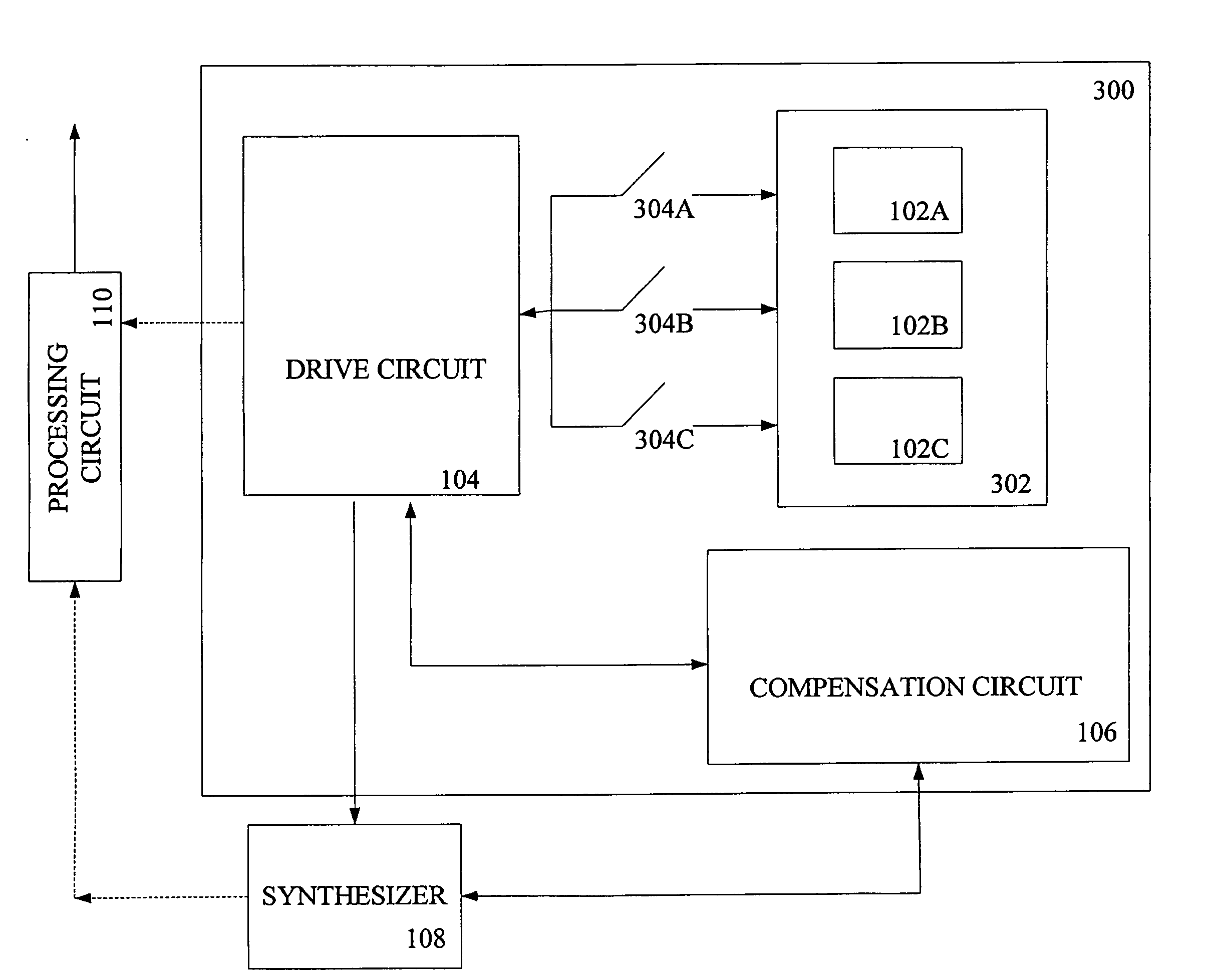
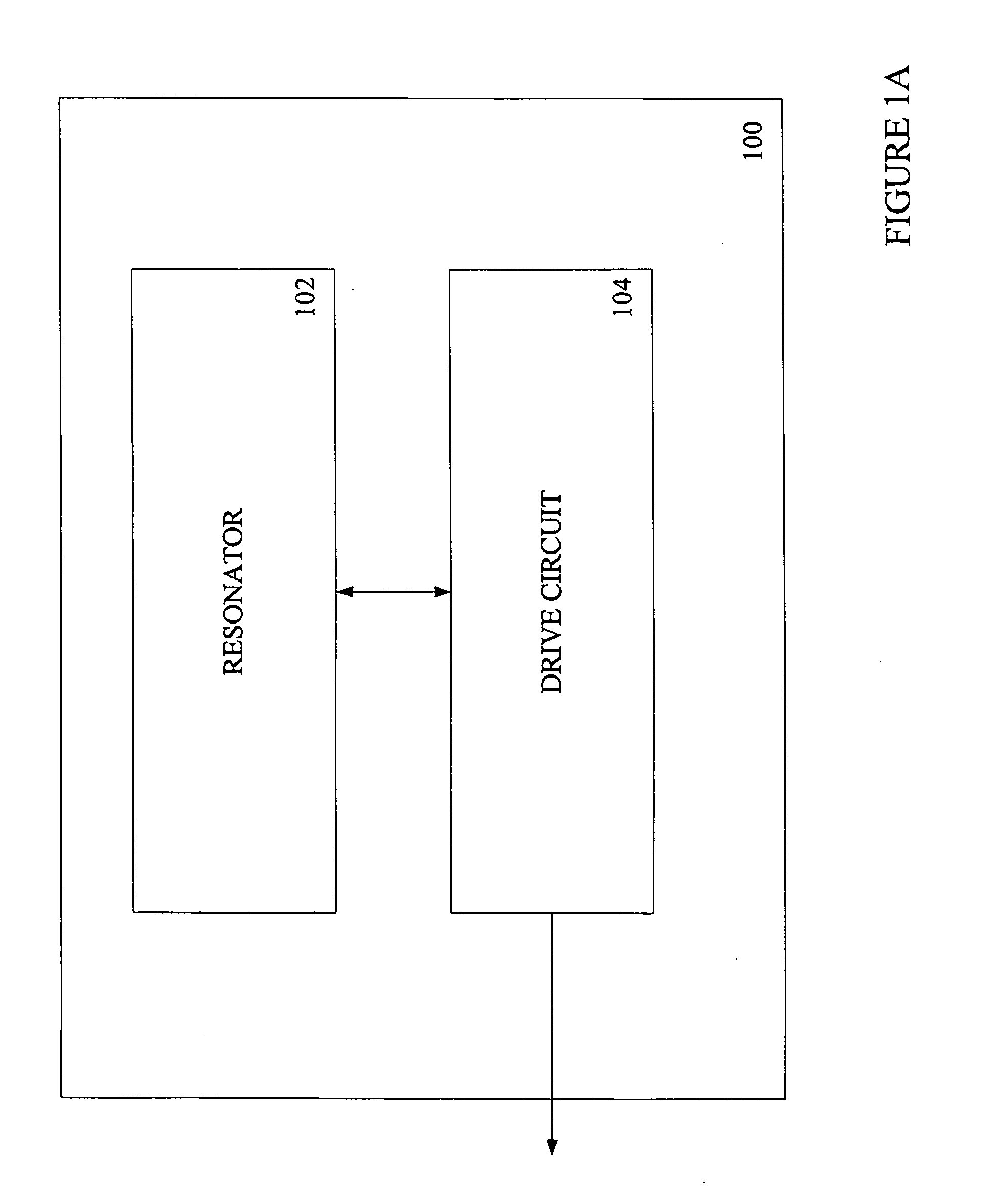
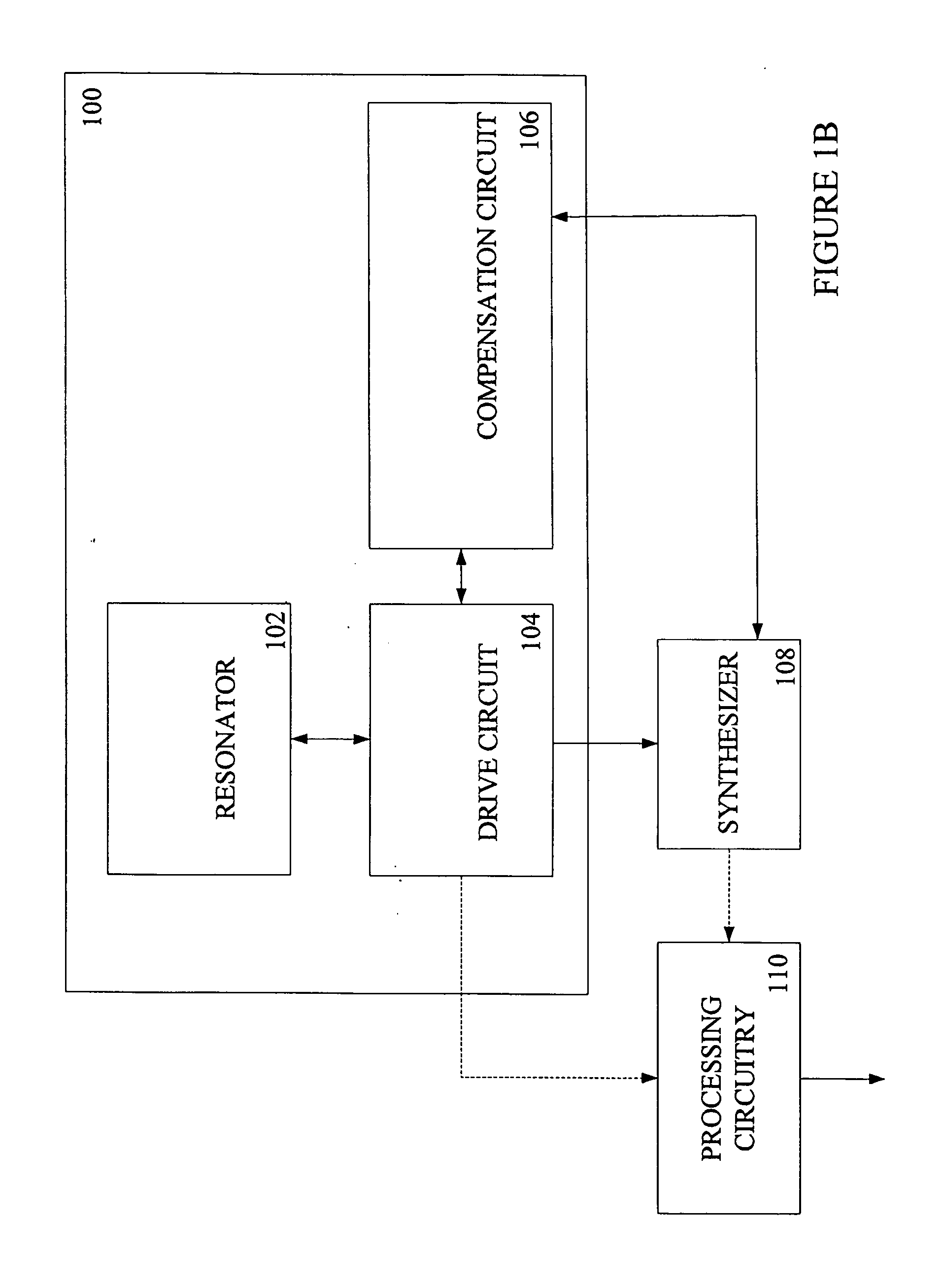
[0023]Timing oscillators are described herein as well as related methods and devices. The timing oscillators may include a mechanical resonating structure. A drive circuit may provide an input signal to the mechanical resonating structure causing it to vibrate. In some embodiments, the mechanical resonating structure comprises more than one element coupled to one another. For example, the resonating structure may include a major element having a micron-scale dimension coupled to one or more minor elements having a nano-scale dimension. In some cases, a compensation circuit is built into the timing oscillator to adjust, or modify, the timing oscillator output signal. The compensation circuit can provide the required adjustments that arise due to several reasons including operational and manufacturing glitches. The timing oscillators may be useful for applications that require generating high frequency signals with low noise and a high Q-factor (quality factor).

[0024]FIG. 1A illustrat...


PUM


Abstract

Timing oscillators as well as related methods and devices are described. A timing oscillator may include a mechanical resonating structure with major elements and minor elements coupled to the major element. The timing oscillator can generate stable signals with low phase noise at very high frequencies which allows a timing oscillator to be used effectively in a number of devices including computers and mobile phones for time and data synchronization purposes. The signal generated by the timing oscillator can be tuned using a driver circuit and a compensation circuit.

Description

FIELD OF INVENTION[0001]The invention relates generally to timing oscillators as well as related methods and devices, and more particularly, to timing oscillators that include a mechanical resonating structure.BACKGROUND OF INVENTION[0002]The generation of high frequency signals has become extremely important due to the increasing use and application of wireless technology and high frequency devices such as personal digital assistants (PDAs) and mobile phones. Currently, several methods and devices can be used to generate high frequency signals. One example is an oscillator, which produces a signal that resonates or vibrates at a specific frequency. There are several types of oscillators. Oscillators can be mechanical, electrical, or a combination of the two, namely electromechanical, in nature. Electro-mechanical oscillators are commonly used because of their ability to generate a stable signal at a precise frequency. An electromechanical oscillator uses the vibrations of a mechani...

Claims


Application Information

Patent Timeline
Patent Type & Authority Applications(United States)
IPC IPC(8): H03B5/30
CPCH03B5/30H03H3/0077H03L7/18H03H2009/02299H03L1/02H03H9/2463
Inventor MOHANTY, PRITIRAJSCHOEPF, KLAUS J.GAIDARZHY, ALEXEIZOLFAGHARKHANI, GUITICHEN, DAVID M.CROWLEY, MATTHEW J.
Owner ANALOG DEVICES INC
Why Eureka
Try Eureka