Semiconductor device for controlling switching power supply

a technology of switching power supply and semiconductor device, which is applied in the direction of electric variable regulation, process and machine control, instruments, etc., can solve the problems of increasing the number of pins in the switching power supply control semiconductor device, increasing the number of pins, and not being desirable in view of the needs. , to achieve the effect of accurately monitoring the variation of the ac input voltag

Active Publication Date: 2009-10-29
FUJI ELECTRIC CO LTD
View PDF2 Cites 32 Cited by
  • Summary
  • Abstract
  • Description
  • Claims
  • Application Information

AI Technical Summary

Benefits of technology

[0012]According to the invention, the starter circuit is turned on / off so that the voltage at the current inflow terminal is detected only in a period in which there is no current flowing into the starter circuit. Accordingly, variation in the AC input voltage can be monitored accurately without influence of impedance from the input AC power source line to the current inflow terminal. Consequently, it is possible to provide a semiconductor device for controlling a switching power supply, in which a voltage detection terminal is used in common as a current inflow terminal so that brown-out detection is enabled without provision of any special input terminal for brown-out detection.

Problems solved by technology

For this reason, there was a problem that the number of pins in the switching power supply control semiconductor device increased.
Because the number of pins in a semiconductor device always needs to be reduced, the increase in the number of pins is not desirable in view of the needs.
Consequently, there was a problem that the number of pins increased because such a pin dedicated for brown-out detection and a pin dedicated for starting current inflow and charging were required.

Method used


Image

  • Semiconductor device for controlling switching power supply
  • Semiconductor device for controlling switching power supply
  • Semiconductor device for controlling switching power supply

Examples


Embodiment Construction

[0016]One or more embodiments of the invention will be described below with reference to the accompanying drawings.

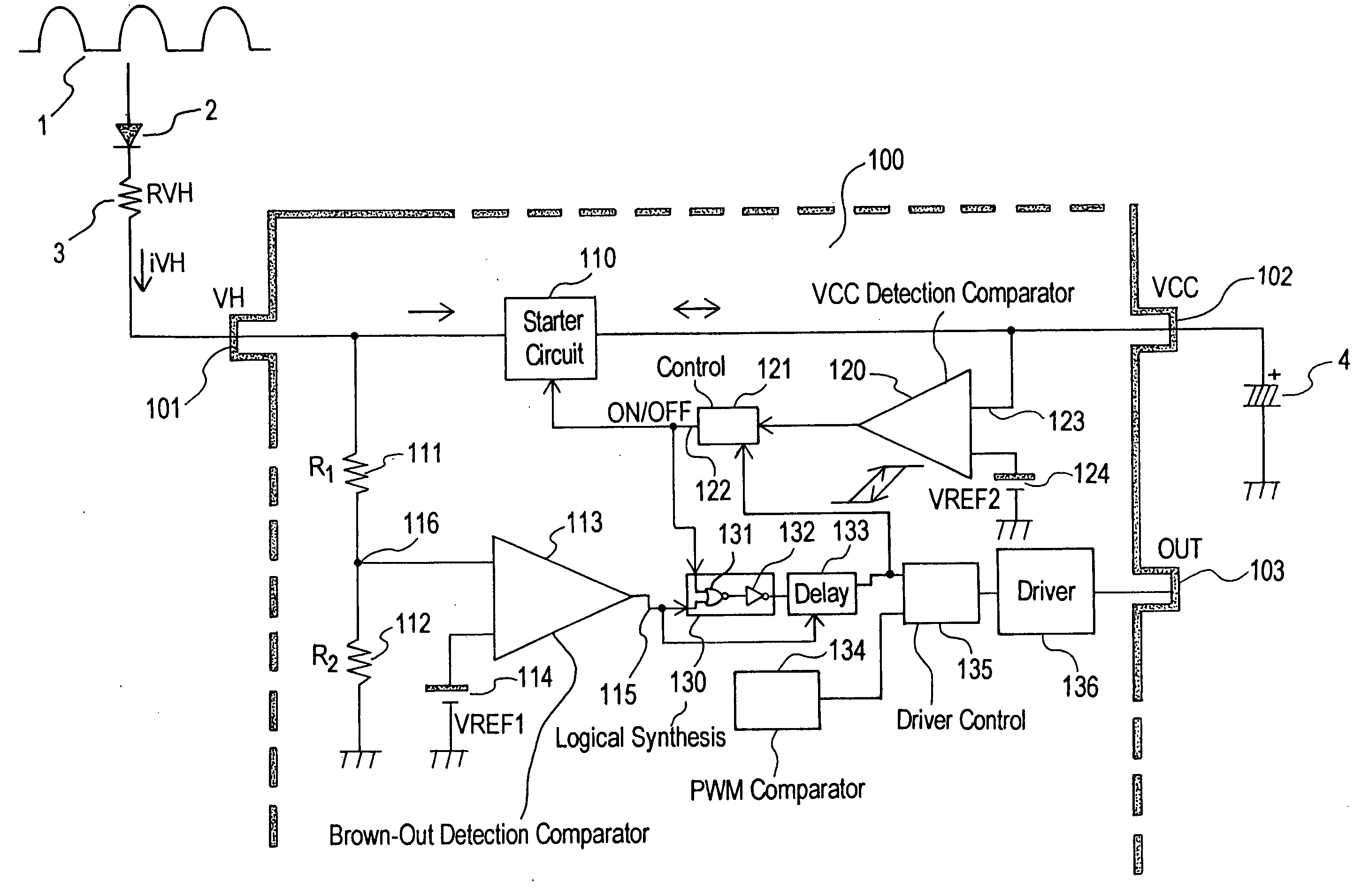
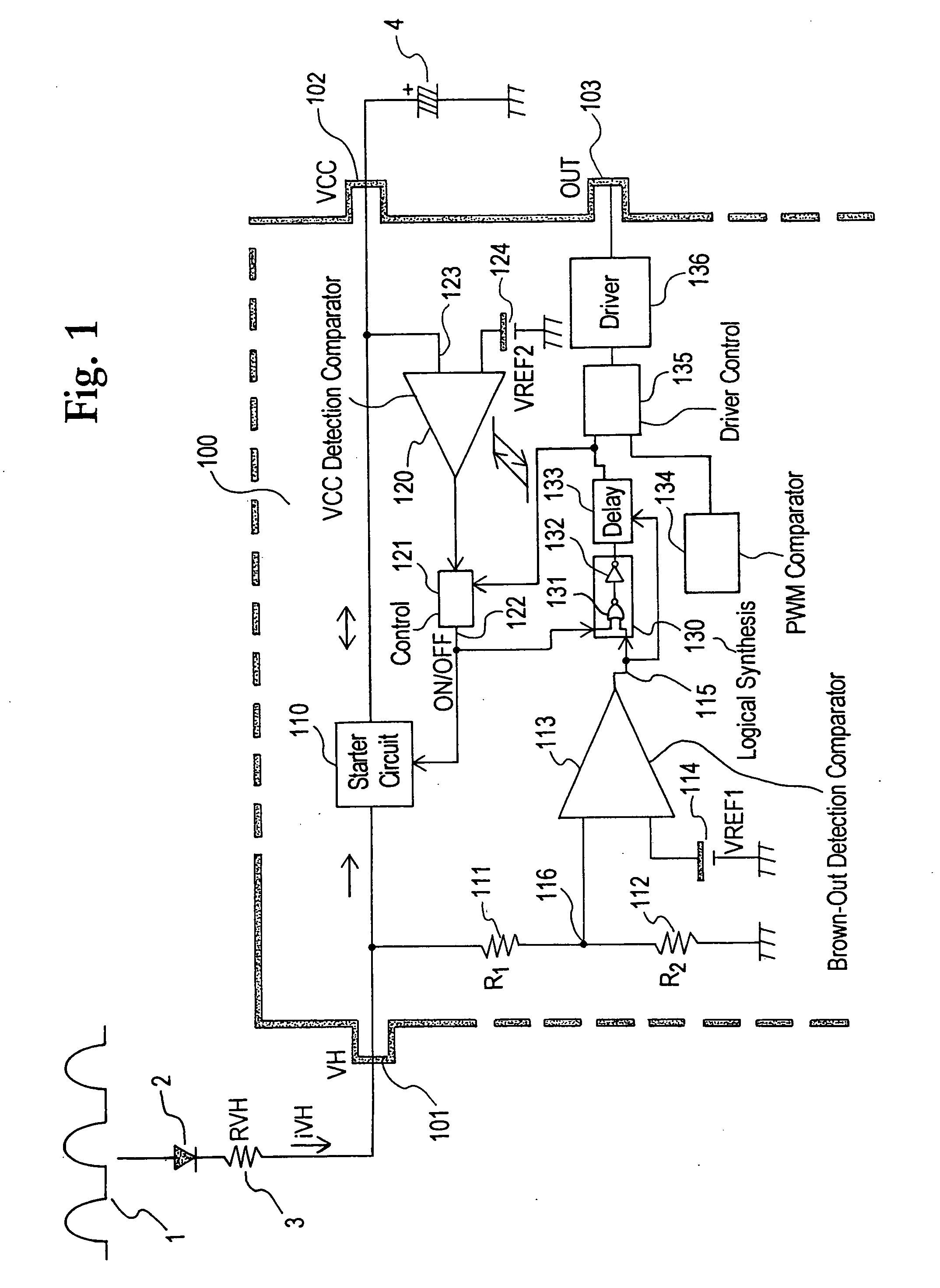
[0017]FIG. 1 is a block diagram showing a configuration of a switching power supply control semiconductor device according to an embodiment of the invention. In FIG. 1, the configuration of the switching power supply control semiconductor device (hereinafter abbreviated to “power supply control IC”) 100 is shown in a dotted line frame provided with protrusions which represent terminals of the power supply control IC 100.

[0018]That is, a terminal VH (101) is a high voltage input terminal to which an AC input voltage 1 obtained by half-wave rectification of a voltage from a commercial power source (not shown) is input. The high voltage input terminal VH (101) serves as a current inflow terminal for allowing a current to flow into a starter circuit (110) and allowing a charging current to flow into a capacitor externally connected to a power supply terminal VCC (which will...


PUM


Abstract

A semiconductor device controls a switching power supply. The semiconductor device includes a current inflow terminal; a starter circuit to cause a starting current to flow from the current inflow terminal to a power supply terminal to charge a capacitor externally connected to the power supply terminal; a control unit which controls the starter circuit to turn on to charge the capacitor with the starting current and controls the starter circuit to turn off to perform brown-out detection; a comparator which detects a brown-out state while the starter circuit is turned off; and a brown-out detection unit which receives output signals from the comparator and the control unit as inputs. The brown-out detection is performed while the starter circuit is off, so that the current inflow terminal for the starter circuit is used in common as a voltage detection terminal for detection of the brown-out state.

Description

BACKGROUND OF THE INVENTION AND RELATED ART STATEMENT[0001]The present invention relates to a semiconductor device for controlling a switching power supply. Particularly it relates to a semiconductor device for controlling a switching power supply, in which brown-out detection can be made without provision of any special input terminal for detecting brown-out (i.e., a voltage drop in an electrical power supply that may cause malfunction of a circuit).[0002]There has been heretofore known a switching power supply control semiconductor device such as a switching power supply control IC having a power supply terminal Vcc, a mute terminal M for suspending a switching operation, an output terminal OUT and a feedback terminal FB, in which a switching element is operated by an output of a voltage detection circuit for detecting an input voltage input to a primary coil of a transformer so that the mute terminal M connected to the switching element is short-circuited to the ground through a ...

Claims


Application Information

Patent Timeline
Patent Type & Authority Applications(United States)
IPC IPC(8): H02M1/00G05F1/00
CPCH02M1/36H02M1/32
Inventor FUJII, MASANARI
Owner FUJI ELECTRIC CO LTD
Why Eureka
Try Eureka