Transducer displacement protection

a technology of displacement protection and transducer, which is applied in the direction of transducer protection circuits, amplification control, electrical apparatus, etc., can solve the problems of limiting affecting the performance of the system,

Active Publication Date: 2009-10-29
BANG & OLUFSEN ICEPOWER
View PDF18 Cites 75 Cited by
  • Summary
  • Abstract
  • Description
  • Claims
  • Application Information

AI Technical Summary

Benefits of technology

[0017]The predictive filter and inverse structure may be updated with a predefined interval based on a measurement of the current in the transducer. For example, the predictive filter and inverse structure may be updated when one or more important properties have changed significantly based on a measurement of the current in the transducers terminals.
[0018]The controlling may be performed by a low pass filter, defining a dynamic behavior of a controller. The input parameters to the dynamic function may be an attack time, release time and displacement threshold, dependent on

Problems solved by technology

In standard loudspeaker systems electro dynamic transducers can fail due to either excessive voice coil excursion, causing mechanical clipping, or by overheating of the voice coil causing degradation of the materials.
Furthermore it describes multiple feedback configurations which do not guaranties a limitation that is fast enoug

Method used


Image

  • Transducer displacement protection
  • Transducer displacement protection
  • Transducer displacement protection

Examples


Embodiment Construction

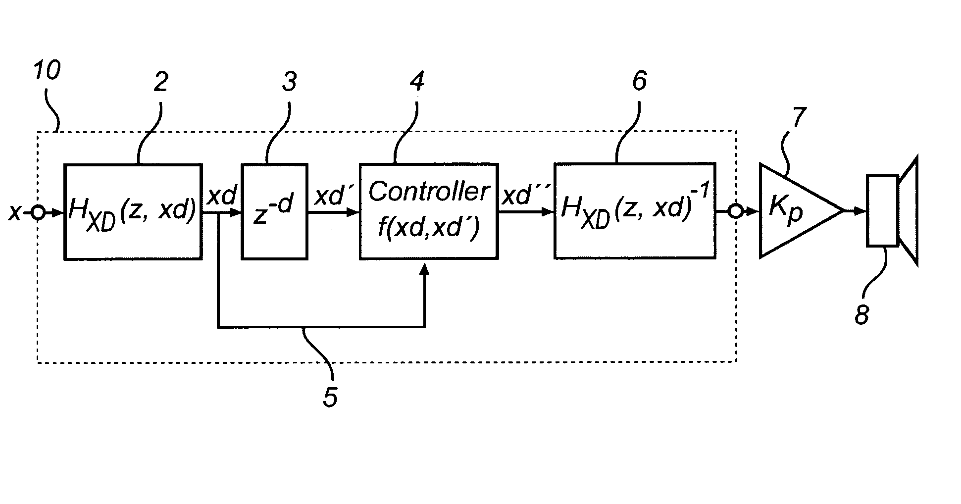
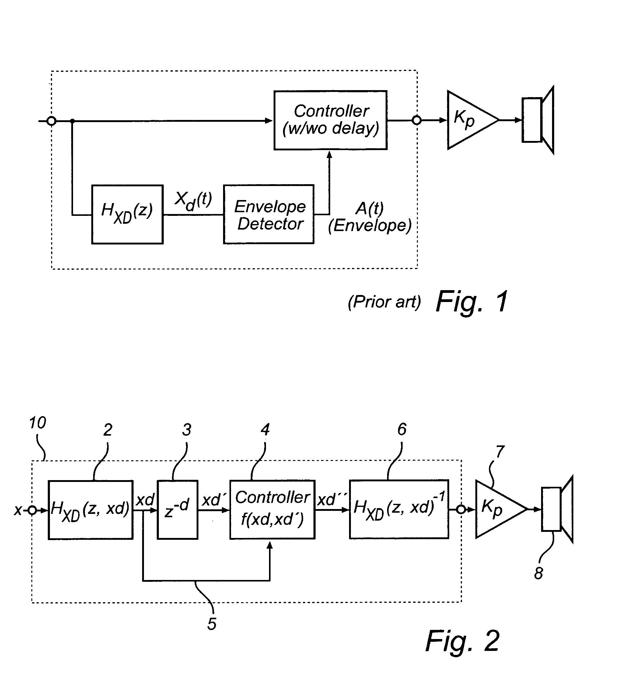
[0044]FIG. 2 displays the overall aspects of a prediction system 10 according to a first embodiment of the present invention. An input signal x is feed to the input of a predictor 2. In a first embodiment of this invention this predictor may comprise a linear filter described by the linear transfer function

H(z)=∑n=0NB(n)z-n∑m=0MA(m)z-m

where H(z) describes the input signal-to-displacement frequency dependent relationship denoted Xd(z) / X(z). In a voltage driven system the input signal will be directly proportional to the voltage applied to the transducer—or in a current driven system; to the current applied to the transducer.

[0045]In one embodiment of the invention the parameters or coefficients are directly extracted from a well know transducer model valid for electro-dynamic transducers, e.g. provided by a Thiele-Small parameterization. For a closed acoustic enclosure the parameters are often modelled as a second order system in which the linear version of the transfer function can ...


PUM


Abstract

This invention relates to the mechanical protection using digital processing and a predictive estimation of instantaneous displacement of the voice coil in a loudspeaker transducer.
The invention solves the problem of limiting the coil displacement of the transducer by applying a look-a-head based linear or non-linear predictor and a controller operating directly on the displacement signal in order to finally convert back into the incoming signal domain.

Description

FIELD OF THE INVENTION[0001]The present invention relates to the mechanical protection of a transducer for use in a loudspeaker using digital processing and a predictive estimation of instantaneous displacement of moving element, e.g. the voice coil in an electro dynamic transducer.[0002]In particular, the present invention relates to a method for protecting transducers in systems where a transducer is part of a loudspeaker and forced to move at the mechanical limit—or even forced by the applied amplification to operate outside the mechanical limit of the transducer itself, causing mechanical clipping and / or distortion if the transducer is not protected and controlled properly.[0003]In this text the term transducer will be used with reference to a single electro dynamic transducer for reproducing sound. The term loudspeaker will be used with reference to an assembly of one or more transducers in some form of cabinet which includes an acoustically closed enclosure, a vented or bass r...

Claims


Application Information

Patent Timeline
IPC IPC(8): H03G11/00
CPCH03G9/025H03G9/005H04R3/007H04R29/003
Inventor SOLGAARD, MADS EMILJENSEN, BJORN SAND
Owner BANG & OLUFSEN ICEPOWER
Why Eureka
Try Eureka