Optical CDMA by Self Heterodyne Filtering

a filtering method and heterodyne technology, applied in the field of optical code division multiple access systems, can solve the problems of large bandwidth required by spectrum spreading, imposing a strong limitation on transmission distance,

Inactive Publication Date: 2009-10-29
BEN GURION UNIVERSITY OF THE NEGEV
View PDF5 Cites 5 Cited by
  • Summary
  • Abstract
  • Description
  • Claims
  • Application Information

AI Technical Summary

Benefits of technology

[0005]The present invention seeks to provide a new passive optical system and method for providing multiple user access to a single transmission medium without the need to allocate separate wavelengths to each user. This is accomplished by means of an OCDMA scheme based on signal coding and channel separation executed in two dimensions—the time dimension using differential delays applied to the signals, and the frequency dimension, used to filter neighboring channels according to the instantaneous differences between frequencies of the time delayed signals. The data-modulation of the optical signal of each channel is achieved by the impression thereon of a small frequency modulation, which switches the frequency of the signal between two data binary values close to the center frequency of the signal, followed by the generation of two mutually time delayed signals from these data-modulated signal. These signals are then transmitted over the transmission medium to a receiver, where the received signals are further differentially time delayed and then detected within a frequency band significantly less than the range of the frequency modulation. By this process, it is possible to discriminate between signals originating from one channel or another according to the time delay used in the receiver. The frequency modulation can be generated either by means of Wavelength Shift Keying (WSK), or by using the chirp frequency shift when switching a DFB laser on and off.

Problems solved by technology

A major drawback of such implementation is the large required bandwidth resulting from spectrum spreading due to channel coding or coherence manipulation.
This imposes a strong limitation on transmission distance.

Method used


Image

  • Optical CDMA by Self Heterodyne Filtering
  • Optical CDMA by Self Heterodyne Filtering
  • Optical CDMA by Self Heterodyne Filtering

Examples


Embodiment Construction

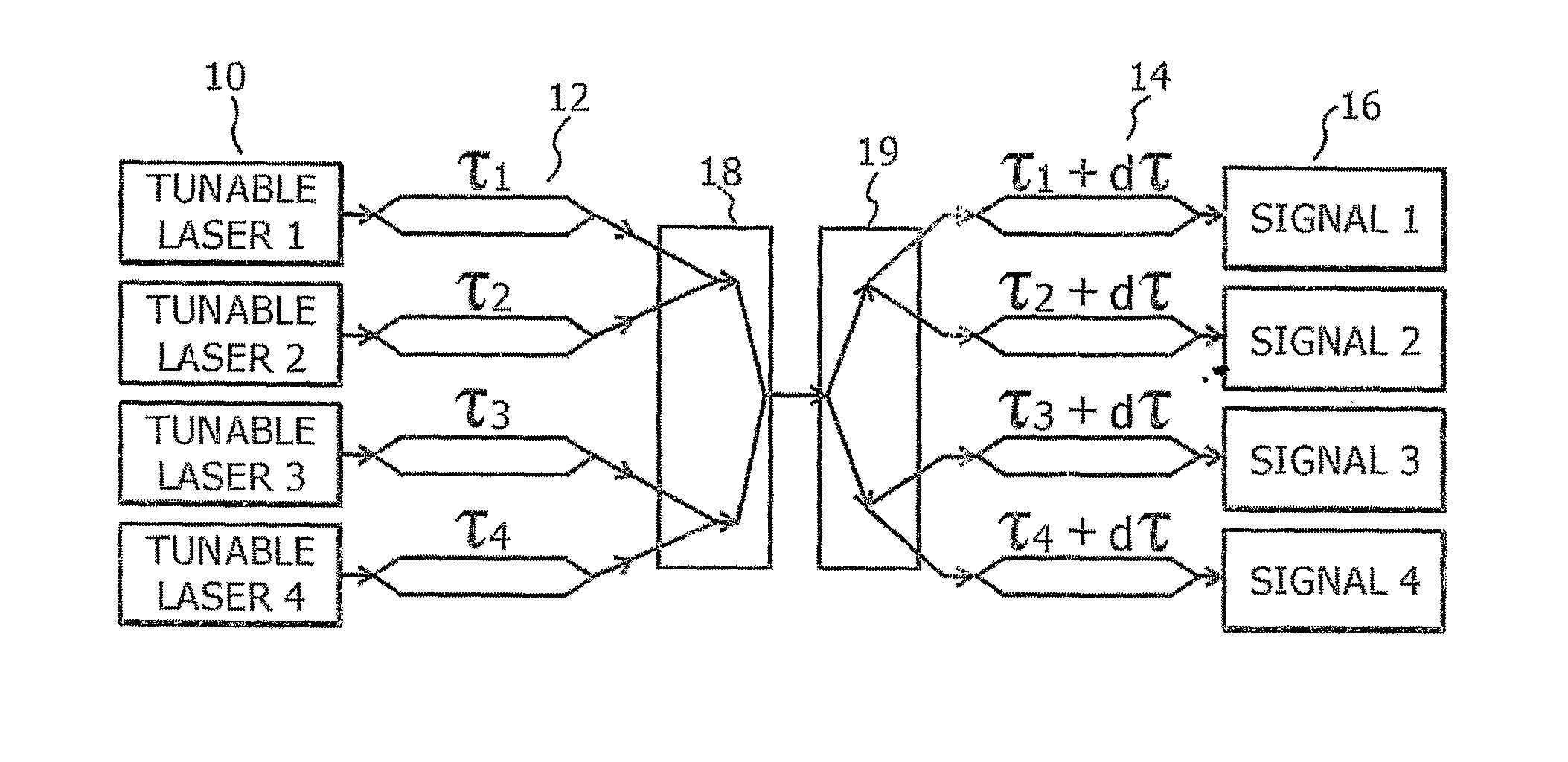
[0047]Reference is now made to FIG. 1, which illustrates schematically a block diagram of an OCDMA system, constructed and operative according to a first preferred embodiment of the present invention, and which illustrates the basic operation of the OCDMA method of the present invention. The preferred embodiment of FIG. 1 comprises only 4 communication channels, but it is to be understood that a practical system may comprise many more channels, and the invention is not intended to be limited only to 4 channels. The transmitter of each communication channel consists of a laser 10, which can be of any common type, such as DBR, GCSR, DFB, FP, VCSEL, MQW, such as are known in the art, and an optical multiplexer 12, while each receiver includes an optical demultiplexer 14 and a regular PIN photodiode detector 16. The outputs of all of the transmitter channels are combined, preferably by means of an optical passive star 18, for dispatch over the transmission medium, and are then distribut...


PUM


Abstract

A new method and system for Optical Code Division Multiple Access (OCDMA) transmission, in which channel selection and rejection are based on dynamic self-heterodyne filtering using differential time delays applied to the data-modulated signals to code and decode the transmissions in each channel. Mach-Zender Interferometers having characteristic delays between their arms are a simple way of performing this coding and decoding. The technique enables the use of narrow linewidth sources and low spectrum spreading. Consequently this technique can be used in next-generation all-optical dynamic networks allowing bandwidth sharing on the one hand, while at the same time eliminating the need for network management and optical switching. Preliminary theoretical calculations predict the system support of up to 15 channels at a data rate of 1 GHz.

Description

FIELD OF THE INVENTION[0001]The present invention relates to the field of Optical Code Division Multiple Access systems, especially as implemented by the use of a self-heterodyne filtering method.BACKGROUND OF THE INVENTION[0002]Optical Code Division Multiple Access (OCDMA) has been recently proposed as an alternative for next-generation access and local area networks (LANs). The motivation for the development of such systems is the need to provide cheap and simple fiber-to-the-home (FTTH) or fiber-to-the-premises (FTTP) systems, preferably based on passive optical networks (PON). The main advantage of OCDMA is the lack of a network management requirement, greatly simplifying the system as compared with, for instance, the use of conventional Wavelength Division Multiple Access (WDMA). There already exist OCDMA systems and the use of coherence multiplexing, implemented as the optical analogies to conventional electronic CDMA systems. Such systems have been described in an article by ...

Claims


Application Information

Patent Timeline
Patent Type & Authority Applications(United States)
IPC IPC(8): H04J14/00
CPCH04J14/005
Inventor JOSEPH, YEHEZKELSADOT, DAN
Owner BEN GURION UNIVERSITY OF THE NEGEV
Why Eureka
Try Eureka