
Encoder/decoder for optical CDMA

a technology of encoder and decoder, applied in the field of encoder/decoder for optical cdma, can solve the problems of fatal error during encoding or decoding, inability to correct encoding, etc., and achieve the effect of accurate decoding at the decoder

Inactive Publication Date: 2007-07-31
PANASONIC CORP
View PDF10 Cites 4 Cited by
  • Summary
  • Abstract
  • Description
  • Claims
  • Application Information

AI Technical Summary

Benefits of technology

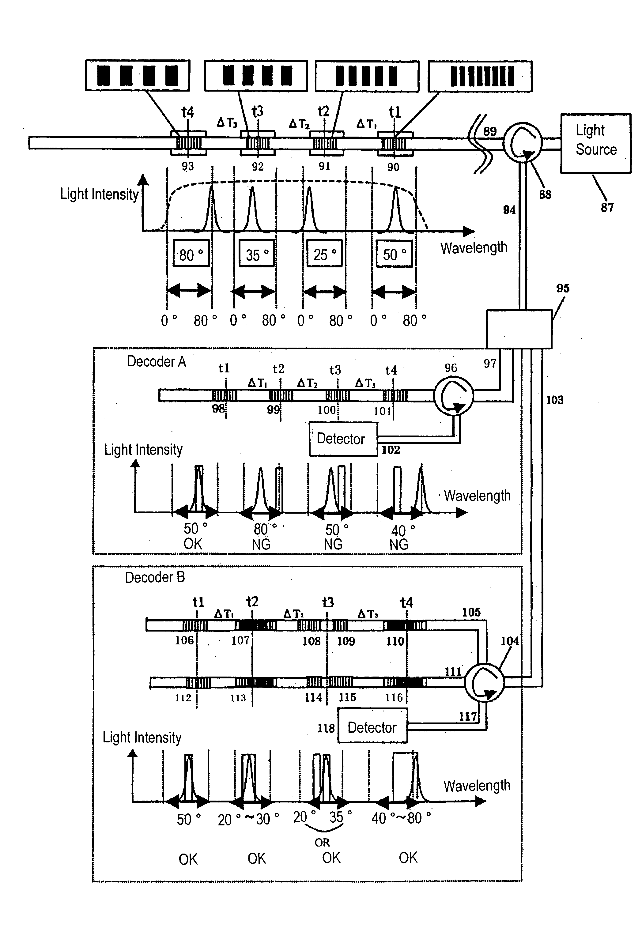
[0044]In accordance with the encoder of the present invention, a plurality of wavelengths are assigned to the same time bin so that, even if a wavelength shift or wavelength drift occurs due to fluctuations in the ambient temperature or tensions applied to the fiber, a shifted wavelength will coincide with an originally-intended wavelength. As a result, even if a wavelength shift occurs, accurate decoding at the decoder is enabled.

Problems solved by technology

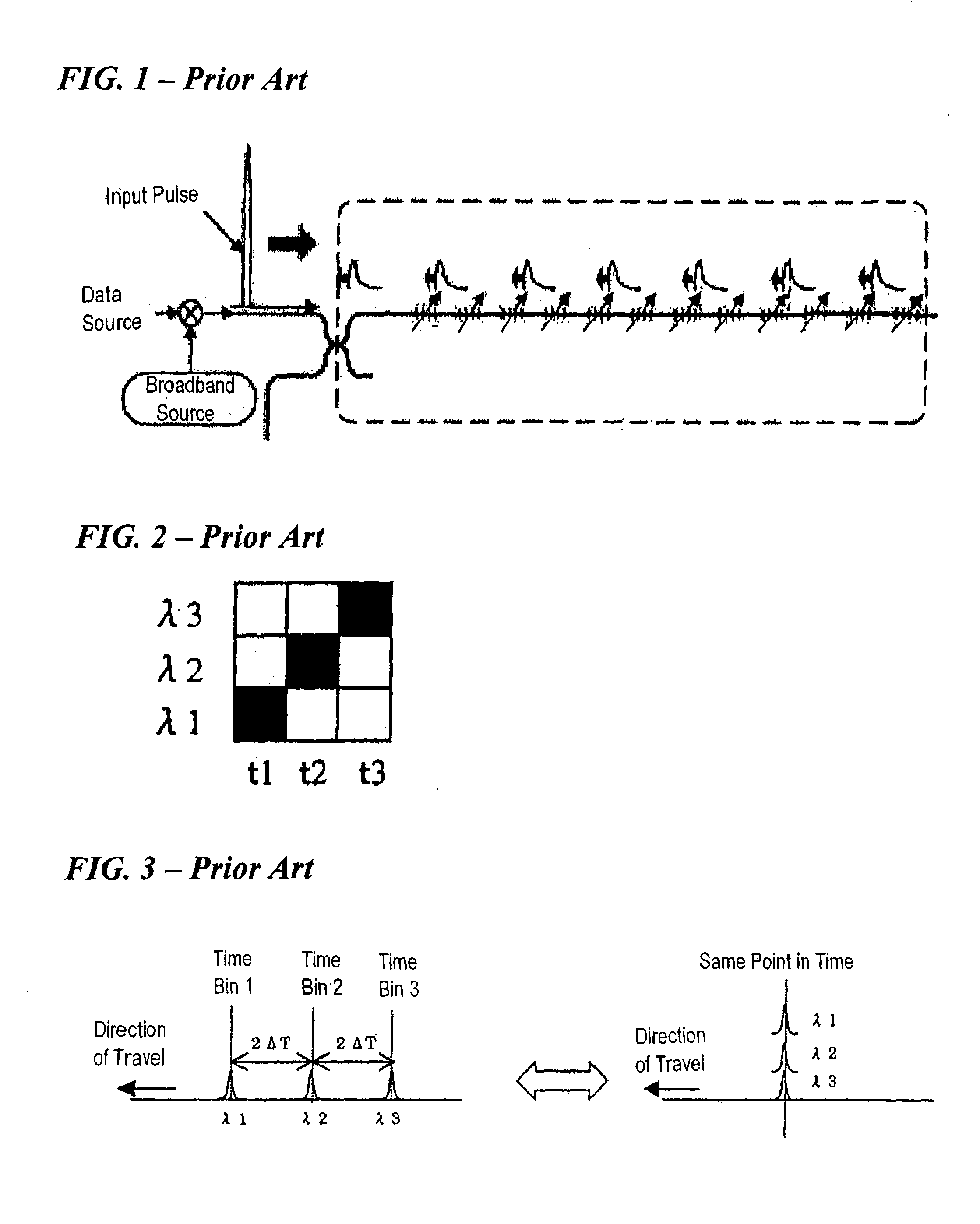
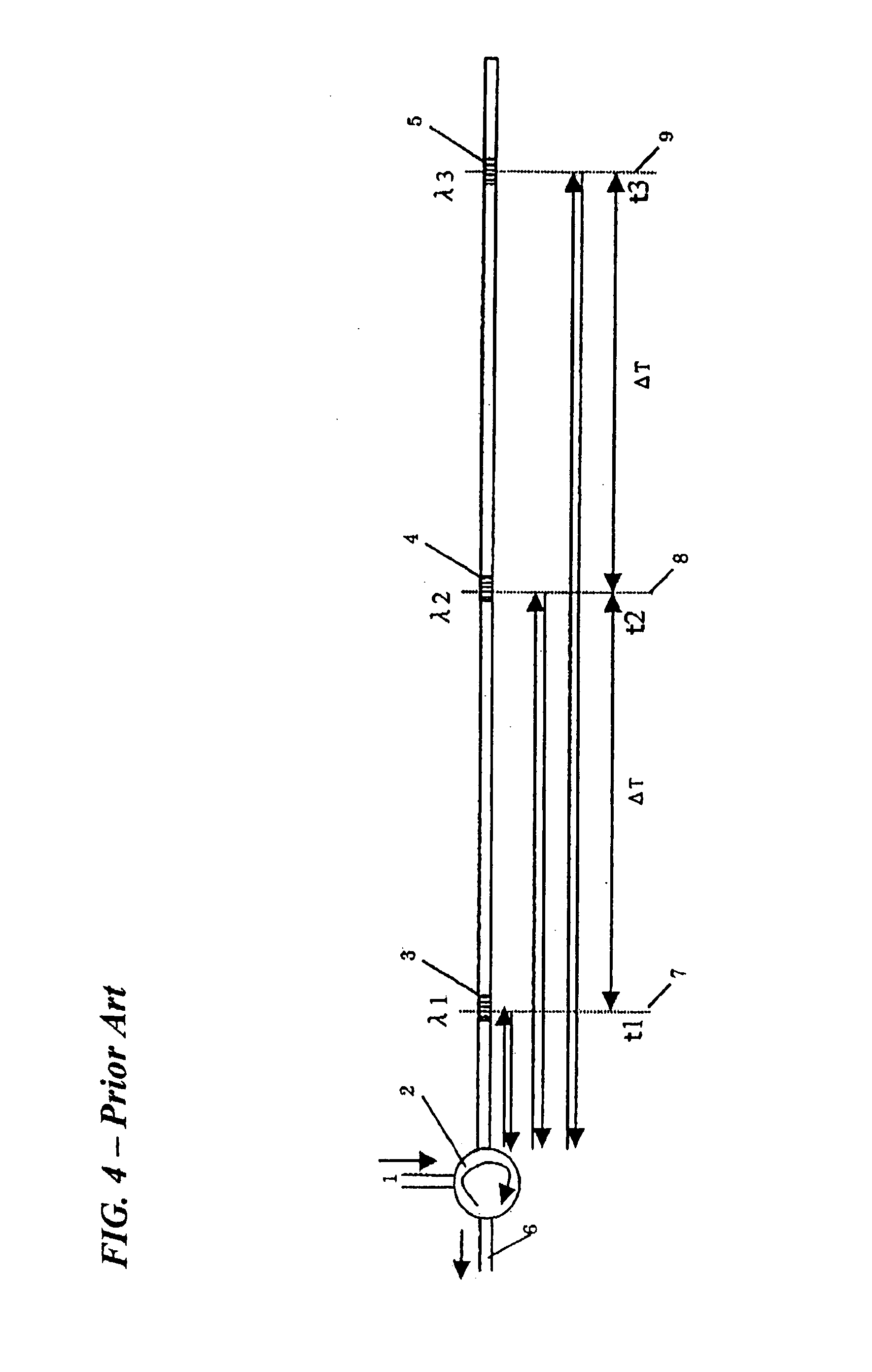
In an encoder having the above structure, if the reflection wavelengths of the gratings are changed due to changes in temperature or application of tension, a so-called “wavelength shift (wavelength drift)” may occur, which makes correct encoding impossible, or in the case of a decoder, makes correct decoding impossible.
Since a code pattern is defined by a combination of a predetermined plurality of reflection wavelengths, a “wavelength shift” can cause a fatal error during encoding or decoding.
For example, if a “wavelength shift” occurs in an encoder, the encoder will perform encoding by using wavelengths which are different from the wavelengths that define the intended code, thus making it impossible for the reciprocal decoder to perform decoding.
Conversely, if a “wavelength shift” occurs in a decoder in the case where encoding has been performed correctly, it becomes impossible to correctly decode the code.
These will induce data transmission errors or transmission failures.
Moreover, as long as a single uniform grating is used for each chip of the code pattern, it will be difficult to provide each reflection wavelength band with a large width.

Method used


Image

  • Encoder/decoder for optical CDMA
  • Encoder/decoder for optical CDMA
  • Encoder/decoder for optical CDMA

Examples


embodiment 1

[0086]Hereinafter, preferable embodiments of the encoder according to the present invention will be described.

[0087]First, FIG. 10 will be referred to. An encoder shown in FIG. 10 is able to perform an encoding according to the code pattern shown in FIG. 8. In other words, a plurality of wavelengths λ1, λ4 and λ5 are assigned to a time bin t1.

[0088]In FIG. 10, an axis 48 indicates a position corresponding to a time bin t1; an axis 49 indicates a position corresponding to a time bin t2; and an axis 50 indicates a position corresponding to a time bin t3. The axis 48 crosses gratings 39 and 43 corresponding to a wavelength λ1; the axis 49 crosses gratings 40 and 46 corresponding to a wavelength λ2; and the axis 50 crosses the gratings 41 and 47 corresponding to a wavelength λ3. Each interval between the axes 48, 49 and 50 constitutes an optical path difference corresponding to a time difference of ΔT / 2. Therefore, as light travels back and forth over each interval, the light receives a...

embodiment 2

[0101]Next, with reference to FIG. 12, other embodiments of the encoder / decoder according to the present invention will be described.

[0102]In Embodiment 1, a group of discrete wavelengths (e.g., λ1, λ4 and λ5) are assigned to the same time bin. In the present embodiment, it is possible to assign a predetermined continuous range of wavelengths (wavelength band) to the same time bin.

[0103]FIG. 11 shows an exemplary code pattern for the apparatus of the present embodiment. In the example of FIG. 11, an infinite number of wavelengths within a continuous range from λ1 to λ1+Δλ are assigned to the time bin t1. Although it would similarly be possible to assign a wavelength range of λ2 to λ2′ to the time bin t2 and a wavelength range of λ3 to λ3′ to the time bin t3, FIG. 11 illustrates an example where wavelengths λ2 and λ3 are assigned, for simplicity.

[0104]A light pulse which has propagated through an optical fiber 53 is transmitted through a circulator 54 to enter a first optical fiber 5...

embodiment 3

[0109]Next, with reference to FIGS. 13 and 14, a third embodiment of the encoder according to the present invention will be described.

[0110]In a code pattern shown in FIG. 13, λ1 and λ1′ are assigned to a time bin t1; λ2 and λ2′ are assigned to a time bin t2; and λ3 and λ3′ are assigned to a time bin t3.

[0111]The encoder of the present embodiment shown in FIG. 14 has a major difference from the encoder of each of the above-described embodiments in that no other grating is inserted between gratings 71, 72, 73, 79, 80 and 81 which are respectively in synchronization with axes 83, 84 and 85 that represent time bins. In the present embodiment, each interval between the axes 83, 84 and 85 is about 0.5 cm, whereas the length of each grating is set to be about 2 cm. Since this structure makes it impossible to adopt the structure shown in FIG. 10 or FIG. 12, the present embodiment adopts the structure of FIG. 14.

[0112]In the present embodiment, as shown in FIG. 14, a light pulse which has p...


PUM

PropertyMeasurementUnit
wavelengthsaaaaaaaaaa
wavelengthaaaaaaaaaa
lengthaaaaaaaaaa

Abstract

An encoder according to the present invention is an encoder for encoding an optical wavelength-multiplexed signal compliant with optical CDMA into a code having a code pattern, including: L optical fibers 36 and 42 (where L is an integer equal to or greater than two) each having a plurality of gratings 37 to 47; and a circulator 52 for coupling the plurality of optical fibers 36 and 42. The code pattern contains time bins t1 to t3. A plurality of wavelengths λ1, λ4 and λ5 are assigned to the time bin t1. If a sum of an optical path difference in each optical fiber from the grating which reflects the optical signal of the wavelength λ1 to the grating which reflects the optical signal of the wavelength λ4 is calculated for all of the optical fibers 36 and 42, the sum equals zero.

Description

[0001]This is a continuation of International Application No. PCT / JP2005 / 019776, with an international filing date of Oct. 27, 2005, which claims priority of Japanese Patent Application No. 2004-323353, filed on Nov. 8, 2004, the contents of which are hereby incorporated by reference.BACKGROUND OF THE INVENTION[0002]1. Field of the Invention[0003]The present invention relates to an apparatus which performs, by optical CDMA (Optical Code Division Multiplex Access), at least one of encoding and decoding of wavelength-division-multiplexed light. More particularly, the present invention relates to an apparatus which employs optical fiber gratings to perform encoding / decoding by optical CDMA.[0004]2. Description of the Related Art[0005]In optical CDMA, a technique similar to the CDMA technology which has been practically used in the field of mobile communications is employed to perform encoding of an optical signal at a transmitting end, and decoding of an optical signal at a receiving e...

Claims


Application Information

Patent Timeline
Patent Type & Authority Patents(United States)
IPC IPC(8): G02B6/34G02B6/12G02F1/295H04B1/7136H04B10/00H04B10/25H04B10/2581H04J13/00H04J14/00H04J14/02H04J14/04H04J14/06
CPCH04J14/005
Inventor ADACHI, JINGOITOH, AKIHIROWAKABAYASHI, SHINICHI
Owner PANASONIC CORP
Learn More