Clamping apparatus for a reciprocating tool

a reciprocating tool and clamping technology, applied in the field of tools, can solve the problems of low degree of automation, and low degree of automation of the known mechanism, and achieve the effects of reducing the amount of particulate matter, and improving the accuracy of clamping

Active Publication Date: 2009-11-05
CREDO TECH CORP +1
View PDF15 Cites 53 Cited by
  • Summary
  • Abstract
  • Description
  • Claims
  • Application Information

AI Technical Summary

Benefits of technology

[0006]a hollow generally cylindrical sleeve secured to the spindle, the sleeve having a radial aperture aligned with the spindle aperture and an annul

Problems solved by technology

While mechanisms are known in the prior art that have this capability, the various known designs have varying degrees of effectiveness in securely holding the tool attachment in the tool, or in the ease and convenience of operation in mounting or removing tool attachments from the tool o

Method used


Image

  • Clamping apparatus for a reciprocating tool
  • Clamping apparatus for a reciprocating tool
  • Clamping apparatus for a reciprocating tool

Examples


Embodiment Construction

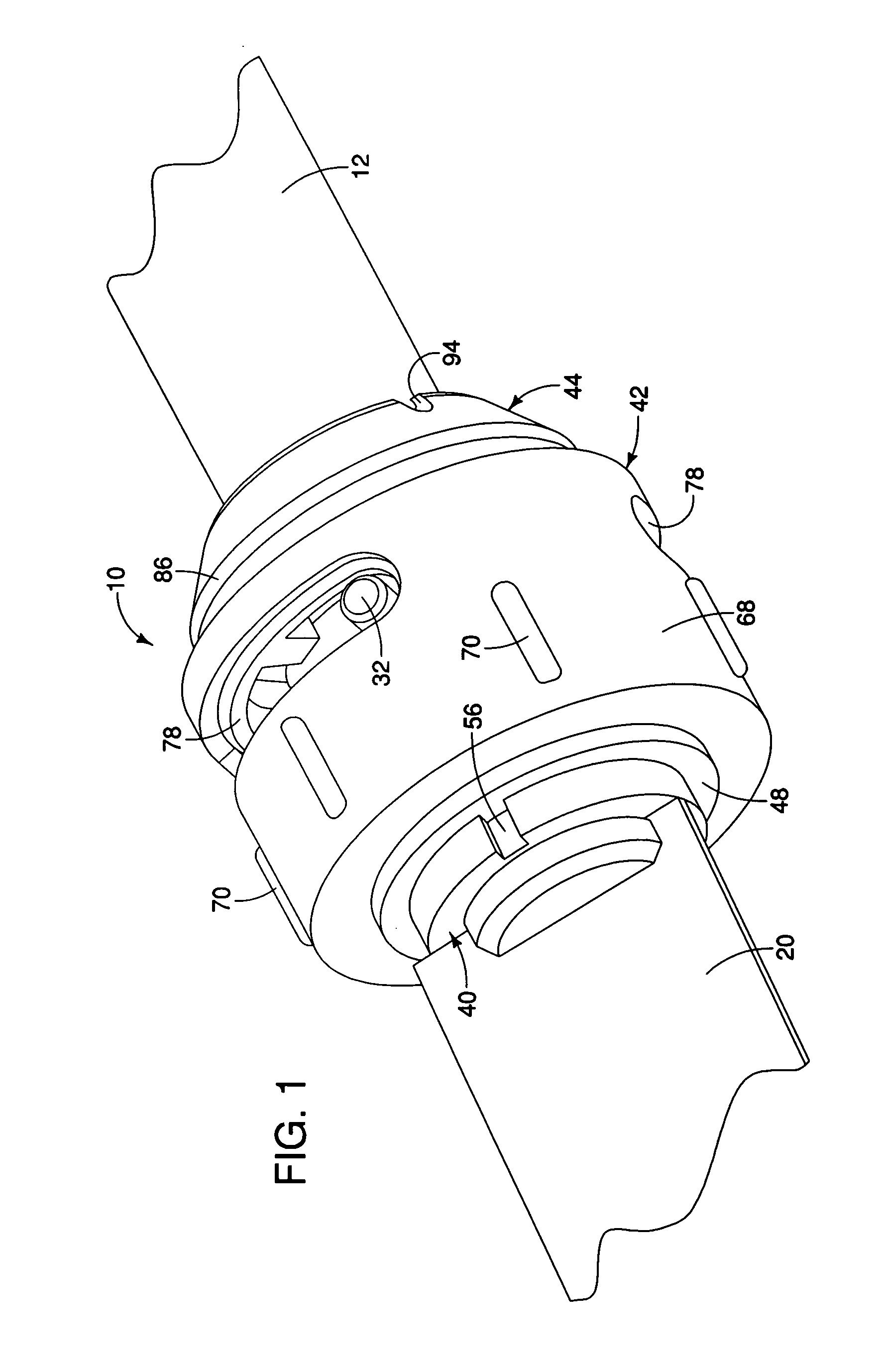
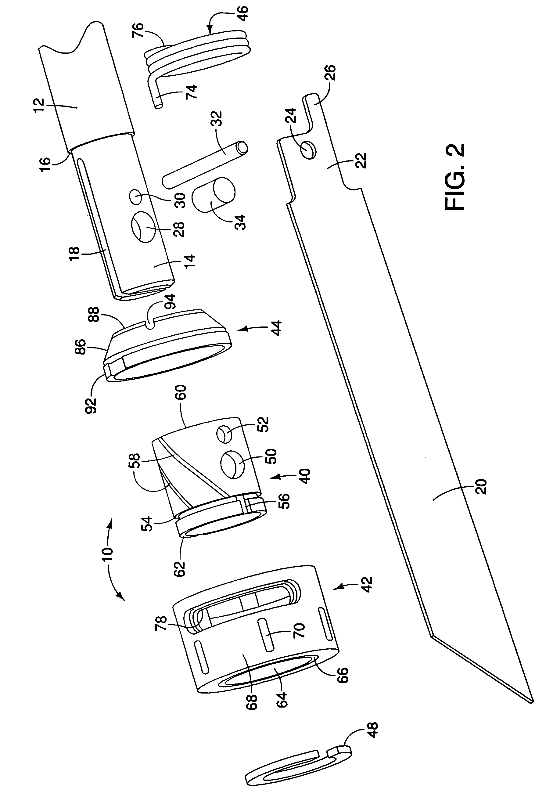
[0016]While embodiments of the present invention can be used with various power hand tools, jig saws, saber saws and other reciprocating saws used in the construction, demolition, metal cutting, and woodworking applications, it should be understood that the clamping apparatus is certainly susceptible for use in applications other than these. It is contemplated that the clamping apparatus may be used in the medical field, particular with surgical instruments that are used with reciprocal saw and cutting blades. Also, while the embodiments of the present invention are particularly suited for use with power hand tools, they could be used with a non-power hand tool as well as larger stationary power tools that employ tool attachments in a reciprocating manner and where such tool attachments are replaced. The detailed description of the preferred embodiments are described with regard to saber and reciprocating saws which use commercially available saw blades. The present invention should...


PUM

PropertyMeasurementUnit
Angleaaaaaaaaaa
Angleaaaaaaaaaa
Forceaaaaaaaaaa

Abstract

Embodiments are disclosed for a tool-less clamping apparatus for a reciprocating tool having a reciprocating spindle having a center axis and at least one radially oriented aperture and a receiving slot at its forward end for receiving a tool accessory, the apparatus having an unclamped position and a clamped position, and comprising a hollow generally cylindrical sleeve secured to the spindle, a hollow generally cylindrical collar configured to fit on the sleeve and being rotatable relative to the spindle and the sleeve, the collar having an inner cam surface that increases in radius from the axis through a first predetermined circumferential arc in a first direction, a spring operatively connected to provide a biasing force to the collar toward its clamped position, and a detent pin positioned in the spindle aperture and configured to engage a hole in the tool accessory and thereby firmly hold the tool accessory in the apparatus when urged into contact with the tool accessory.

Description

BACKGROUND OF THE INVENTION [0001]The present invention generally relates to tools, and more particularly, to mechanisms for clamping tool accessories to such tools.[0002]Reciprocating tools such as jigsaws, saber saws and the like have been the subject of extensive research and development efforts over the years. A focus of many designers is the mechanisms for attaching a tool attachment such as a cutting blade, a saw blade, an abrasive, polishing or smoothing member or the like to the reciprocating portion of such tools.[0003]Early attachment mechanisms required separate tools of one kind or another, typically screwdrivers, wrenches or levers, to attach the tool attachment to a reciprocating member by tightening screws or the like. Because special tools were often required, it was necessary to have such tools available during use in the event the tool attachment breaks or otherwise needs to be changed because it is worn out or a different type of tool attachment is needed.[0004]Re...

Claims


Application Information

Patent Timeline
IPC IPC(8): B23D51/08B27B19/00
CPCB23D51/10Y10T279/17803Y10T279/17761Y10T279/17717Y10T279/17777Y10T279/3493Y10T279/17923
Inventor DEZHENG, ZHENGMICHEL, TIMOTHY P.KRONDORFER, HARALD
Owner CREDO TECH CORP
Why Eureka
Try Eureka