System and method for assessing the proximity of an electrode to tissue in a body

Active Publication Date: 2009-11-05
ST JUDE MEDICAL ATRIAL FIBRILLATION DIV
View PDF75 Cites 230 Cited by
  • Summary
  • Abstract
  • Description
  • Claims
  • Application Information

AI Technical Summary

Benefits of technology

[0010]The present invention is directed to a method and system for assessing proximity between an electrode and tissue. The system according to the present teachings includes an electronic control unit (ECU). The ECU is configured to acquire values for first and second components of a complex

Problems solved by technology

Arrhythmia can create a variety of dangerous conditions including irregular heart rates, loss of synchronous atrioventricular contractions and stasis of blood flow which can lead to a variety of ailments and even death.
If the electrode is too far from the tissue or has insufficient contact with the tissue, the lesions created may not be effective.
On the other hand, if the catheter tip containing the electrode contacts the tissue with excessive force, the catheter tip may perforate or otherwise damage the tissue (e.g., by overheating).
While in many conventional systems catheter position and speed are known, knowledge relating to the proximity of a catheter electrode to tissue, or contact therebetween, is somewhat challenging.
These challenges arise, at least in part, from the precision required and factors such as posture of the patient, ventilation, and cardiac contraction.
While such techniques may be useful in sensing or assessing the existence and magnitude or degrees of contact between the electrode and the tissue, they present disadvantages with respect to assessing proximity of the electrode to the tissue.
One major drawback of using such techniques to assess proximity is that proximity information cannot be determined until after contact with the tissue has been made.
Accordingly, these techniques do not provide the necessary information until it is effectively too late, since contact has already been made and proximity information post-contact is essentially useless.

Method used


Image

  • System and method for assessing the proximity of an electrode to tissue in a body
  • System and method for assessing the proximity of an electrode to tissue in a body
  • System and method for assessing the proximity of an electrode to tissue in a body

Examples


Embodiment Construction

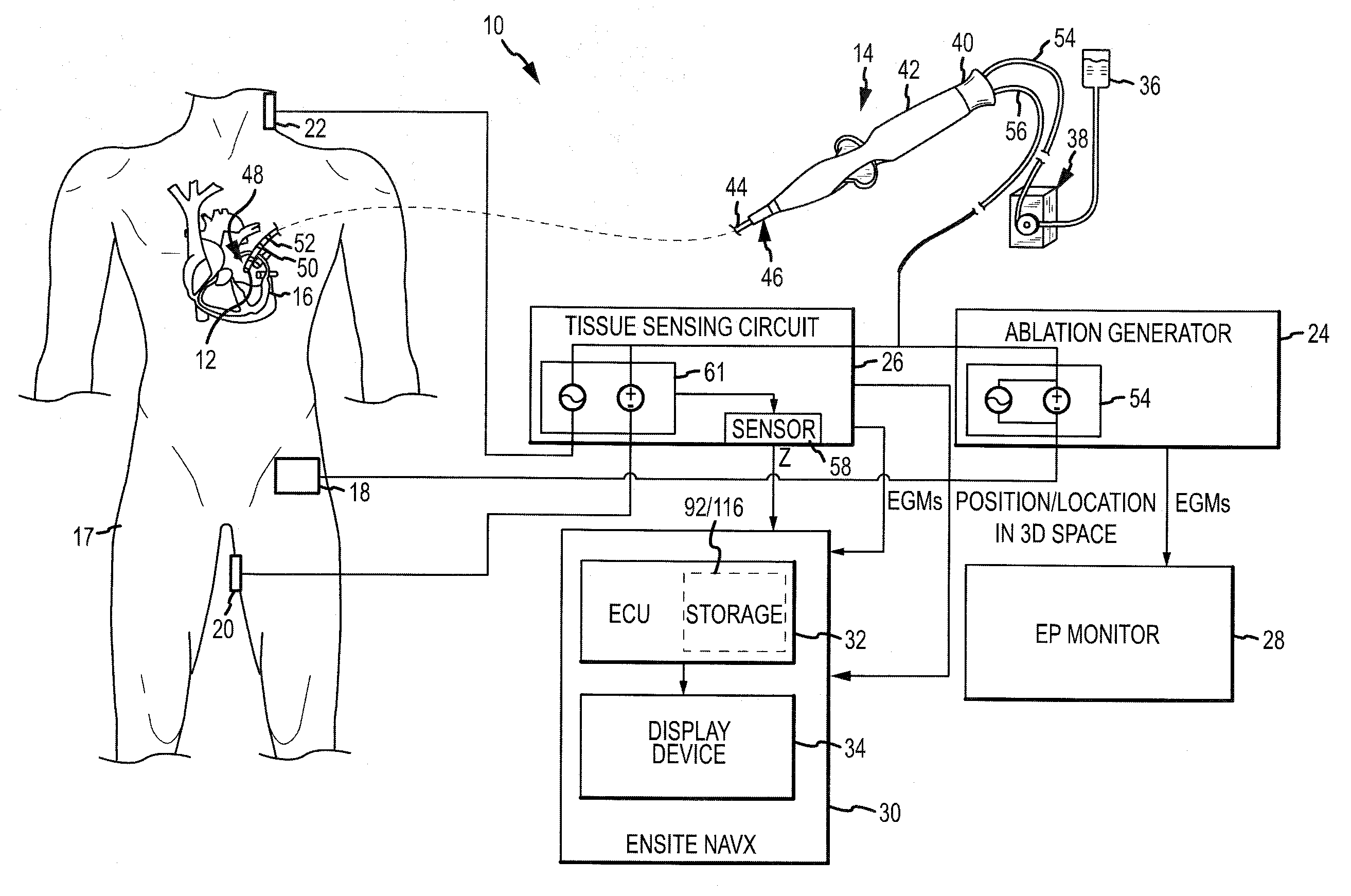
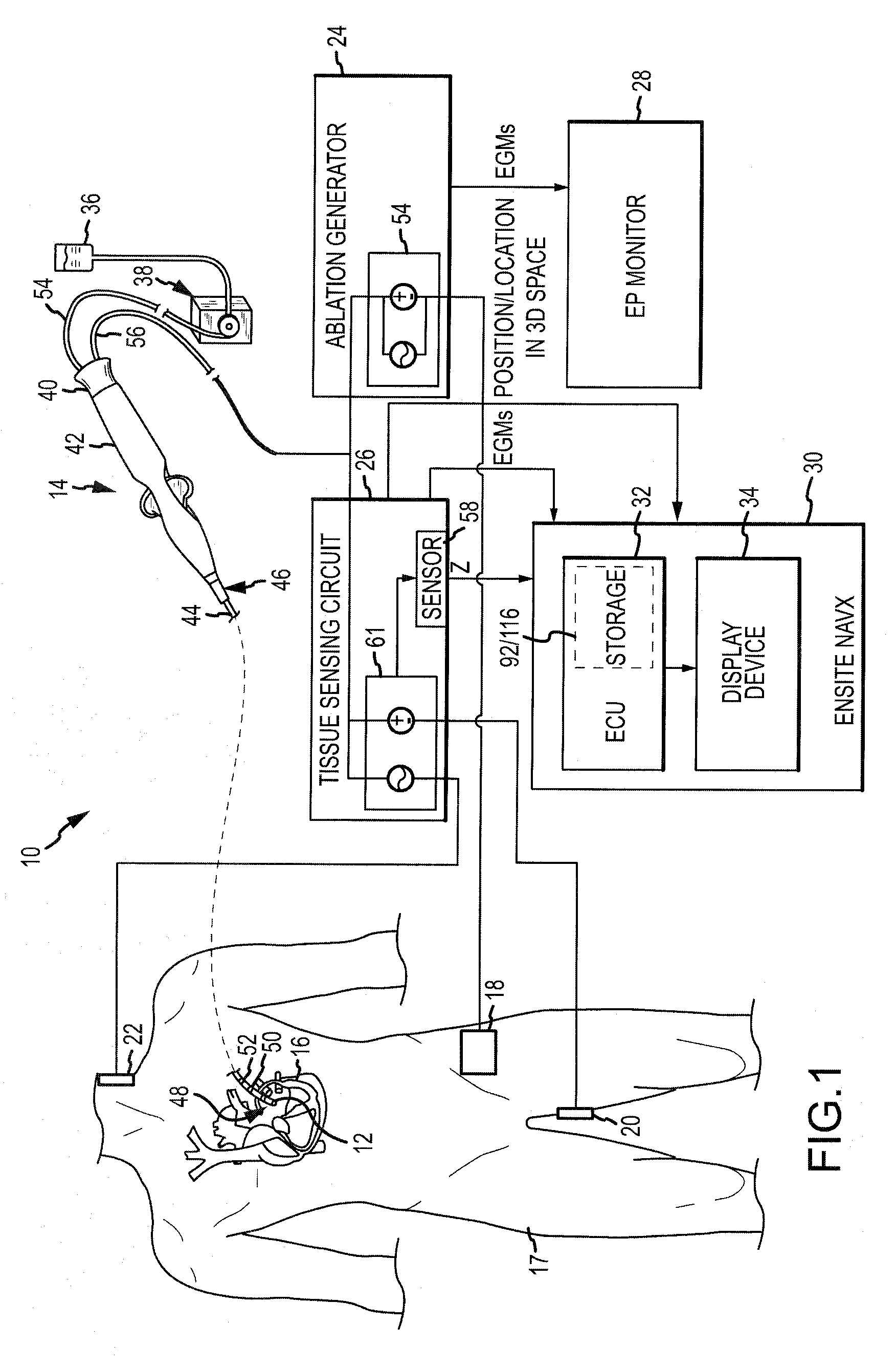
[0030]Referring now to the drawings wherein like reference numerals are used to identify identical components in the various views, FIG. 1 illustrates one embodiment of a system 10 for one or more diagnostic and therapeutic functions including components providing an improved assessment of, among other things, a degree of coupling between an electrode 12 on a catheter 14 and a tissue 16 in a body 17. As will be described in greater detail below, the degree of coupling can be useful for assessing, among other things, the degree of contact between the electrode 12 and the tissue 16, as well as the relative proximity of the electrode 12 to the tissue 16. In the illustrated embodiment, the tissue 16 comprises heart or cardiac tissue. It should be understood, however, that the present invention may be used to evaluate coupling between electrodes and a variety of body tissues. Further, although the electrode 12 is illustrated as part of the catheter 14, it should be understood that the pr...


PUM


Abstract

A method and system for assessing proximity between an electrode and tissue is provided. The system includes an electronic control unit (ECU). The ECU is configured to acquire values for first and second components of a complex impedance between the electrode and the tissue, and to calculate an electrical coupling index (ECI) responsive to the first and second values. The ECU is further configured to process the ECI to determine the proximity of the electrode to the tissue. The ECU may be configured to calculate an electrical coupling index rate (ECIR) based on the calculated ECI and information relating to the change in location of the electrode, and to assess proximity based on the ECIR. Alternatively, the ECU may be configured to assess the proximity using the calculated ECI, as opposed to the ECIR.

Description

[0001]This application is a continuation-in-part of U.S. patent application Ser. No. 12 / 253,637 filed Oct. 17, 2008, the entire disclosure of which is incorporated by reference, which is a continuation-in-part of U.S. patent application Ser. No. 12 / 095,688 filed May 30, 2008, the entire disclosure of which is also incorporated herein by reference. U.S. patent application Ser. No. 12 / 095,688 is a national stage application of, and claims priority to, International Application No. PCT / US2006 / 061714 filed Dec. 6, 2006, the entire disclosure of which is incorporated herein by reference. The International Application was published in the English language on Jun. 14, 2007 as International Publication No. WO 2007 / 067941 A2 and itself claims the benefit of U.S. Provisional Patent Application No. 60 / 748,234 filed Dec. 6, 2005, the entire disclosure of which is incorporated herein by reference.BACKGROUND OF THE INVENTION[0002]a. Field of the Invention[0003]This invention relates to a system a...

Claims


Application Information

Patent Timeline
IPC IPC(8): A61B5/053
CPCA61B5/053A61B5/0538A61B5/06A61B18/1206A61B5/068A61B18/16A61B2218/002A61B5/063A61B18/1492
Inventor AIKEN, ROBERT D.DENO, D. CURTISKASTNER, GLEN H.MILLER, STEPHAN P.
Owner ST JUDE MEDICAL ATRIAL FIBRILLATION DIV
Why Eureka
Try Eureka