Stent Graft Delivery System and Method of Use

a technology of stent graft and delivery system, which is applied in the field of stent graft delivery system and method of use, can solve the problems of high mortality rate, long hospital stay, and long recovery tim

Inactive Publication Date: 2009-11-05
MEDTRONIC VASCULAR INC
View PDF6 Cites 204 Cited by
  • Summary
  • Abstract
  • Description
  • Claims
  • Application Information

AI Technical Summary

Problems solved by technology

While open surgery was and is an effective surgical technique in light of the high risk associated with a fatal abdominal aortic aneurysm rupture, the open surgical technique suffers from a number of disadvantages.
It is complex, requires a long hospital stay, requires a long recovery time, and has a high mortality rate.
When the stent graft is allowed to expand in such curves without constraining the proximal end of the stent graft, it may tilt unpredictably to an undesired position.
Such tilting can reduce the effectiveness of the seal and contribute to inaccurate placement.
This movement may damage the vessel and some misalignment may remain.
If the nose cone is inadvertently advanced in the vessel, axial misplacement of the stent graft will result and possibly undesired contact with sensitive structure such as the aortic valve.

Method used


Image

  • Stent Graft Delivery System and Method of Use
  • Stent Graft Delivery System and Method of Use
  • Stent Graft Delivery System and Method of Use

Examples


Embodiment Construction

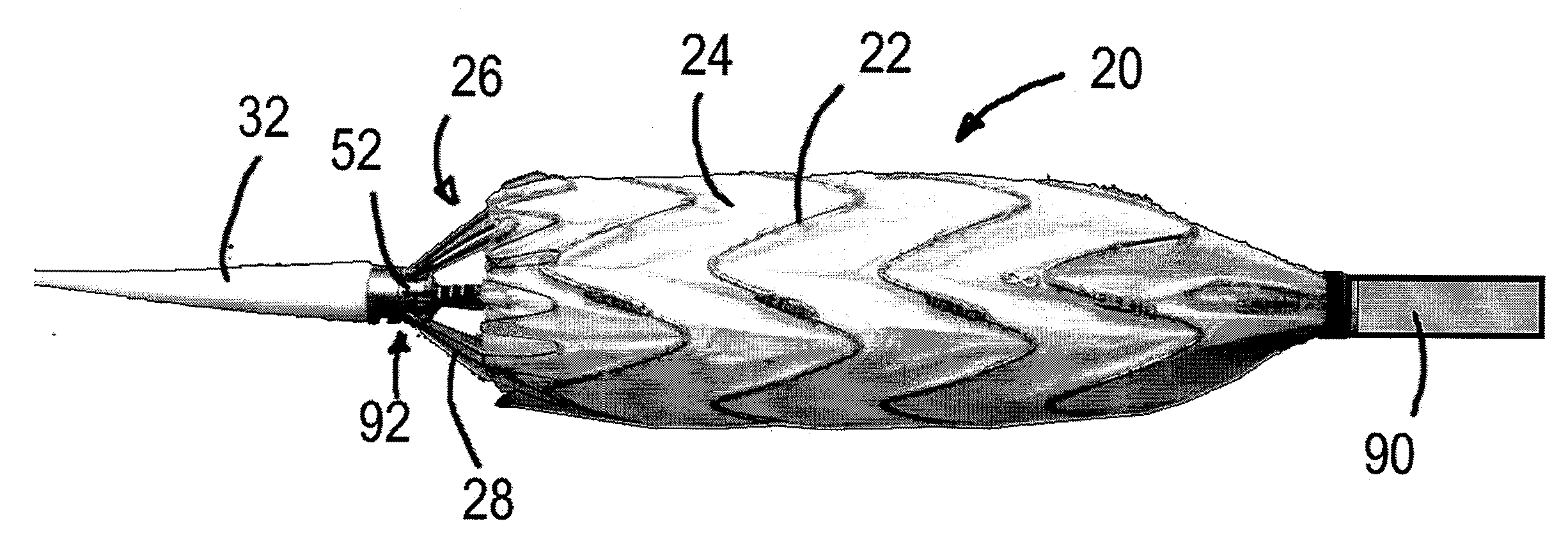
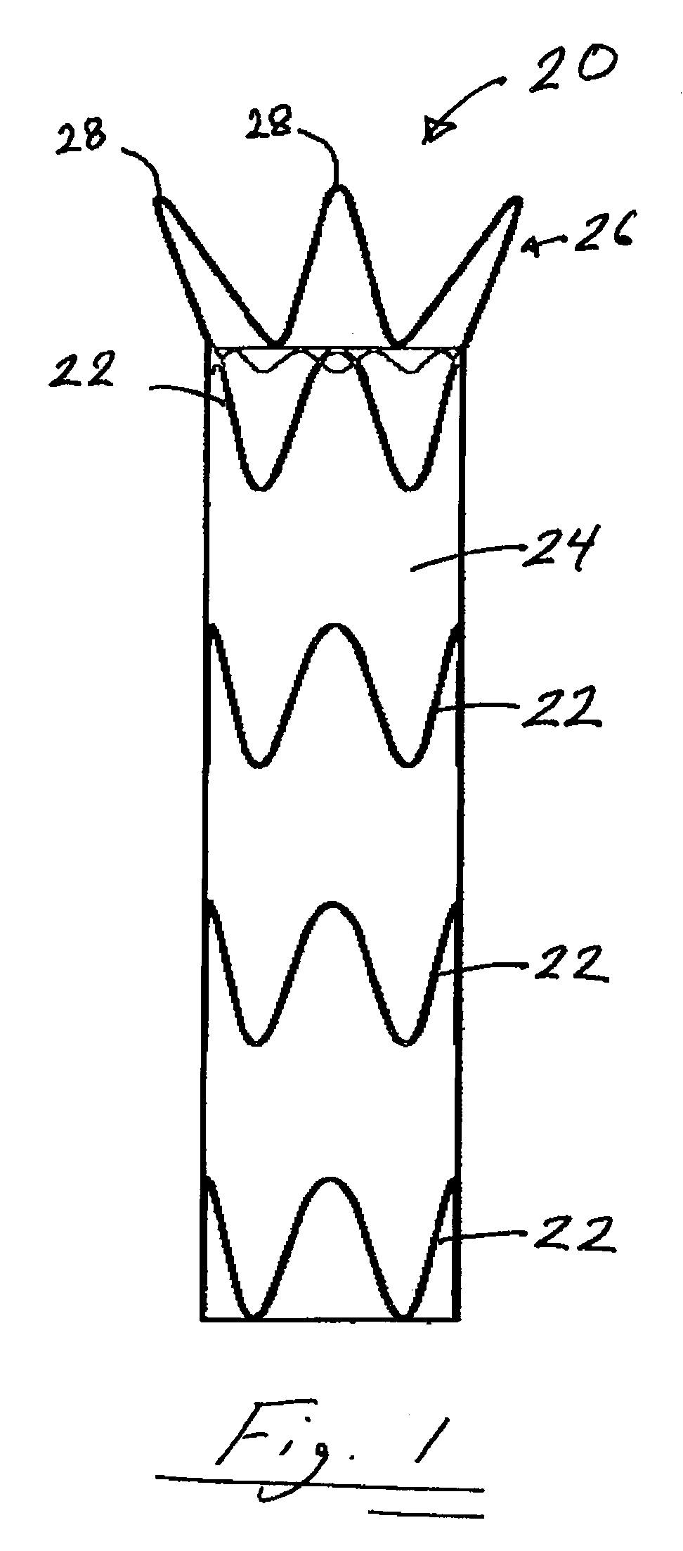
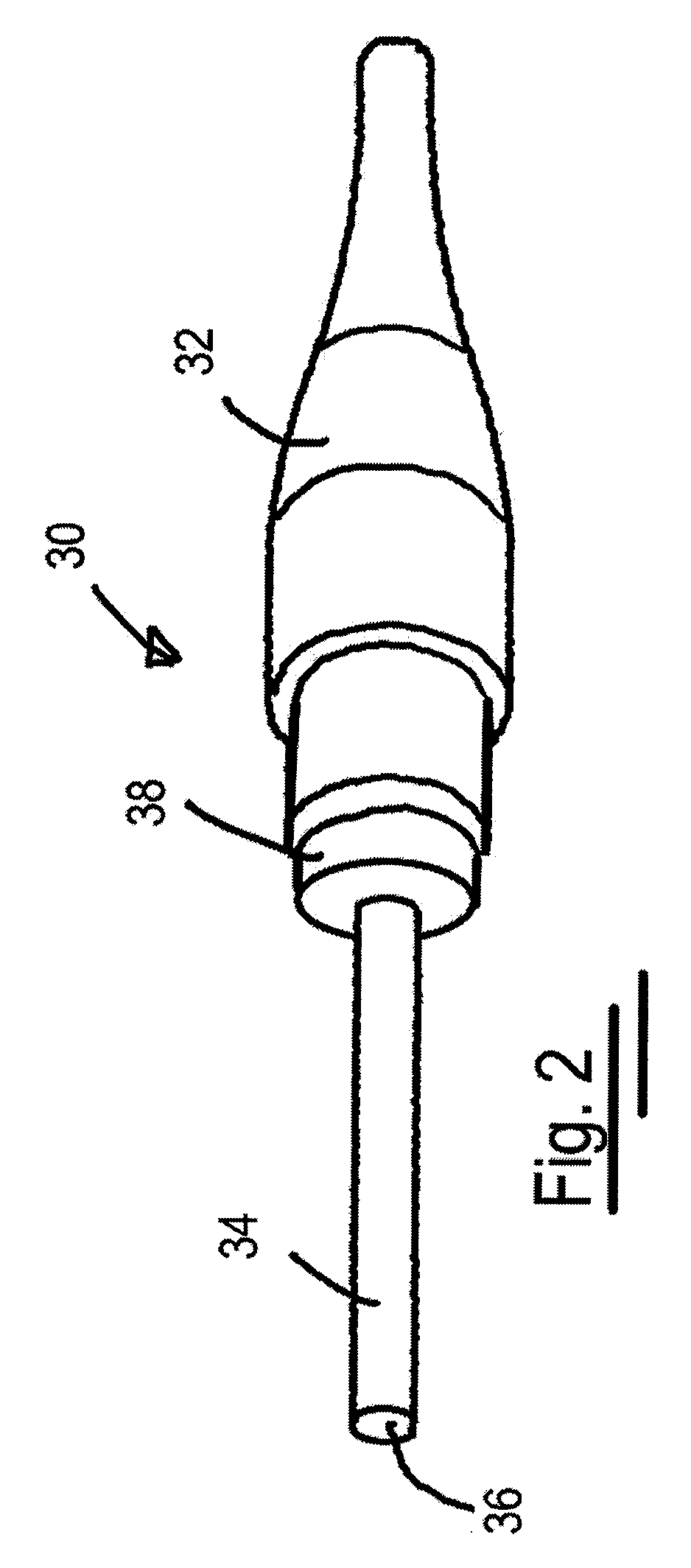
[0028]Embodiments according to the invention will now be described by reference to the figures wherein like numbers refer to like structures. The terms “distal” and “proximal” for the delivery system are used herein with reference to the treating clinician during the use of the stent graft delivery system: “distal” indicates a portion of the stent graft delivery system distant from, or a direction away from the clinician and “proximal” indicates a portion of the stent graft delivery system near to, or a direction towards the clinician. The terms “distal” and “proximal” for the stent graft are used herein with reference to the direction of blood flow from the patient's heart to and through the stent graft device: proximal” indicates a portion of the stent graft nearest the heart according to the blood flow path from the heart to the device, “distal” indicates a portion of the stent graft distant from heart according to blood flow path, or the end opposite the proximal end. In the exa...


PUM


Abstract

A stent graft delivery system and method of use including a delivery system for a stent graft including a nosecone assembly having a nosecone and a nosecone shaft; a spindle assembly defining a spindle assembly lumen through which the nosecone shaft can slide, the spindle assembly having a spindle fitting and a spindle shaft; and a stent capture assembly defining a stent capture assembly lumen through which the spindle shaft can slide, the stent capture assembly having a stent capture fitting and a stent capture shaft. The spindle fitting is slidably mateable with the stent capture fitting to retain an end of the stent graft at a delivery diameter. A stent graft delivery system with an end stent capture configuration providing both a primary and a secondary deployment procedure facilitated by the threaded connection between a bare stent crown spindle fitting and a system nosecone.

Description

TECHNICAL FIELD[0001]The technical field of this disclosure is medical implantation devices, particularly, a stent graft delivery system and method of use.BACKGROUND OF THE INVENTION[0002]Wide ranges of medical treatments have been developed using endoluminal prostheses, which are medical devices adapted for temporary or permanent implantation within a body lumen, such as naturally occurring or artificially made lumens. Examples of lumens in which endoluminal prostheses may be implanted include lumens such as those located within coronary, mesentery, peripheral, or cerebral vasculature; arteries; gastrointestinal tract; biliary tract; urethra; trachea; hepatic shunts; and fallopian tubes. Various types of endoluminal prostheses have also been developed with a particular structure to modify the mechanics of the targeted vessel wall.[0003]A number of vascular devices have been developed for replacing, supplementing, or excluding portions of blood vessels. These vascular devices includ...

Claims


Application Information

Patent Timeline
Patent Type & Authority Applications(United States)
IPC IPC(8): A61F2/06A61B19/00
CPCA61F2/07A61F2002/9505A61F2/95A61F2/966A61F2002/9665
Inventor GLYNN, BRIAN
Owner MEDTRONIC VASCULAR INC
Why Eureka
Try Eureka