
Guaranteed memory card performance to end-of-life

Active Publication Date: 2009-11-05
SANDISK TECH LLC
View PDF0 Cites 43 Cited by
  • Summary
  • Abstract
  • Description
  • Claims
  • Application Information

AI Technical Summary

Benefits of technology

[0004]The disclosed embodiments act to offset the performance degradation such that a memory system can maintain a performance level to the end-of-life.
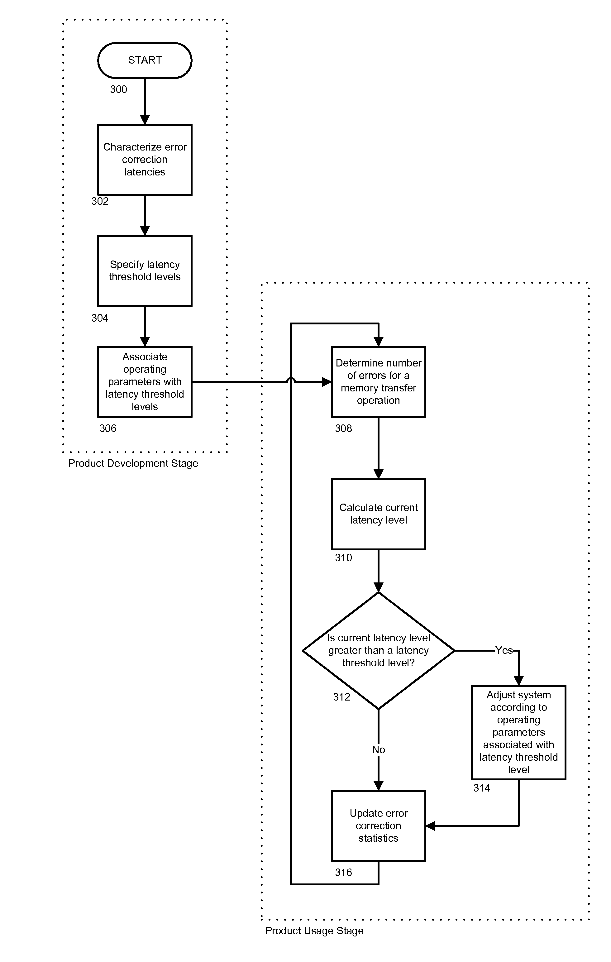
[0006]According to another embodiment of the present invention, error correction statistics are collected and stored by the memory system, in real-time and preferably according to predetermined memory transfer sizes. These error correction statistics are used to calculate a current latency level, which is then dynamically compared with previously established error correction latency threshold levels. If the current latency level is greater than or equal to a specific error correction latency threshold level, then the memory system's configuration is adjusted according to operating parameters associated with that threshold level to offset the increased error correction latency such that the memory system can maintain its performance levels.
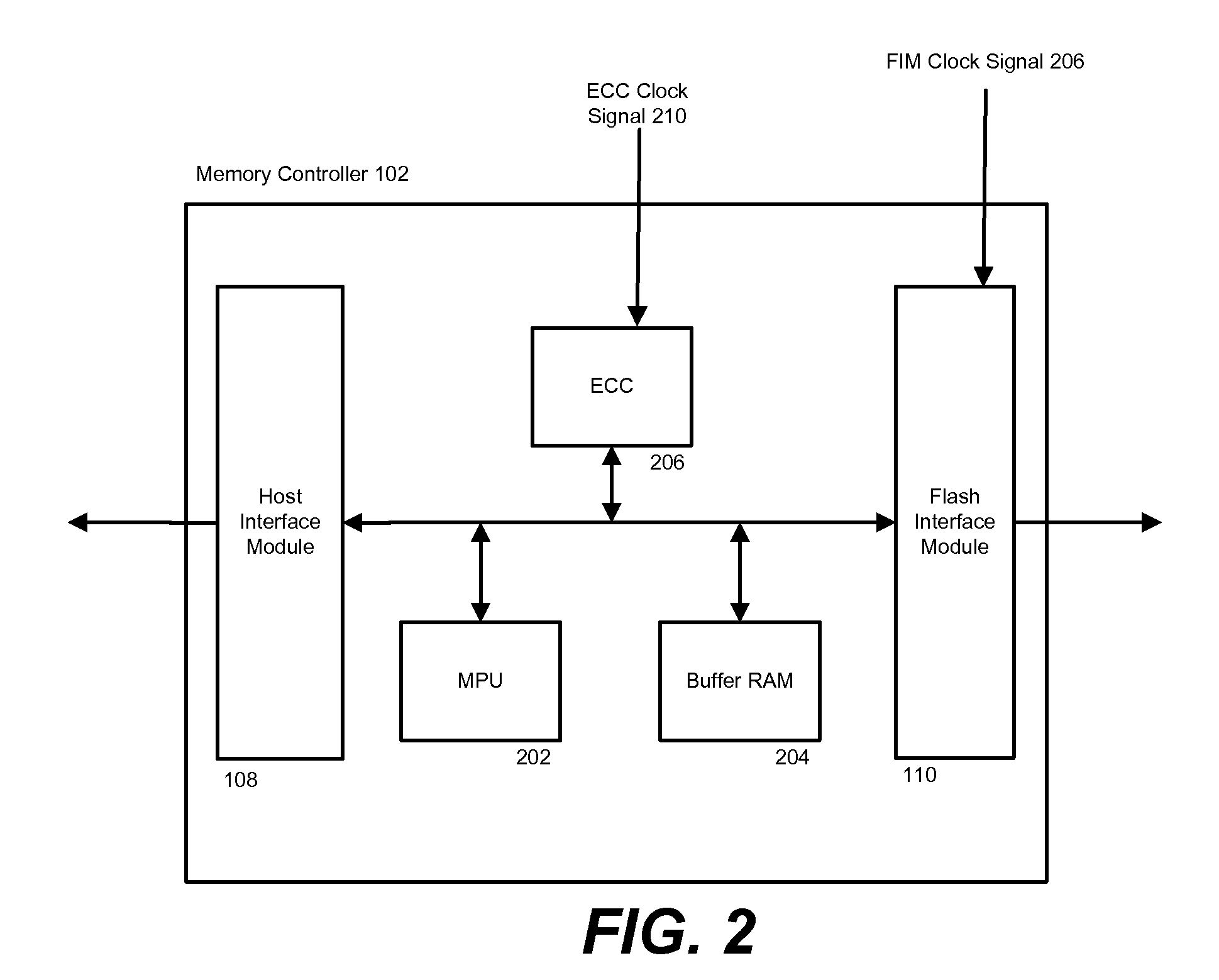
[0008]In another embodiment of the present invention, a memory system includes two ECC circuits which can be operated in parallel to quickly correct memory errors. As the memory system gathers and stores error correction statistics, a current memory rate can be dynamically calculated using the error correction statistics. This current memory error rate can be compared to previous memory error rates, and as the memory error rate increases, the second ECC circuit can be enabled and / or operated at a faster speed to help correct the increased number of memory errors.

Problems solved by technology

In many memory systems, degradation occurs with use over time, which prevents the memory system from maintaining its performance levels to its end-of-life.
Degradation of the memory contributes to an increase of memory errors, which in turn leads to longer overall transfer times due in part to latency in transfers as more errors are detected and require correction.

Method used


Image

  • Guaranteed memory card performance to end-of-life
  • Guaranteed memory card performance to end-of-life
  • Guaranteed memory card performance to end-of-life

Examples


Embodiment Construction

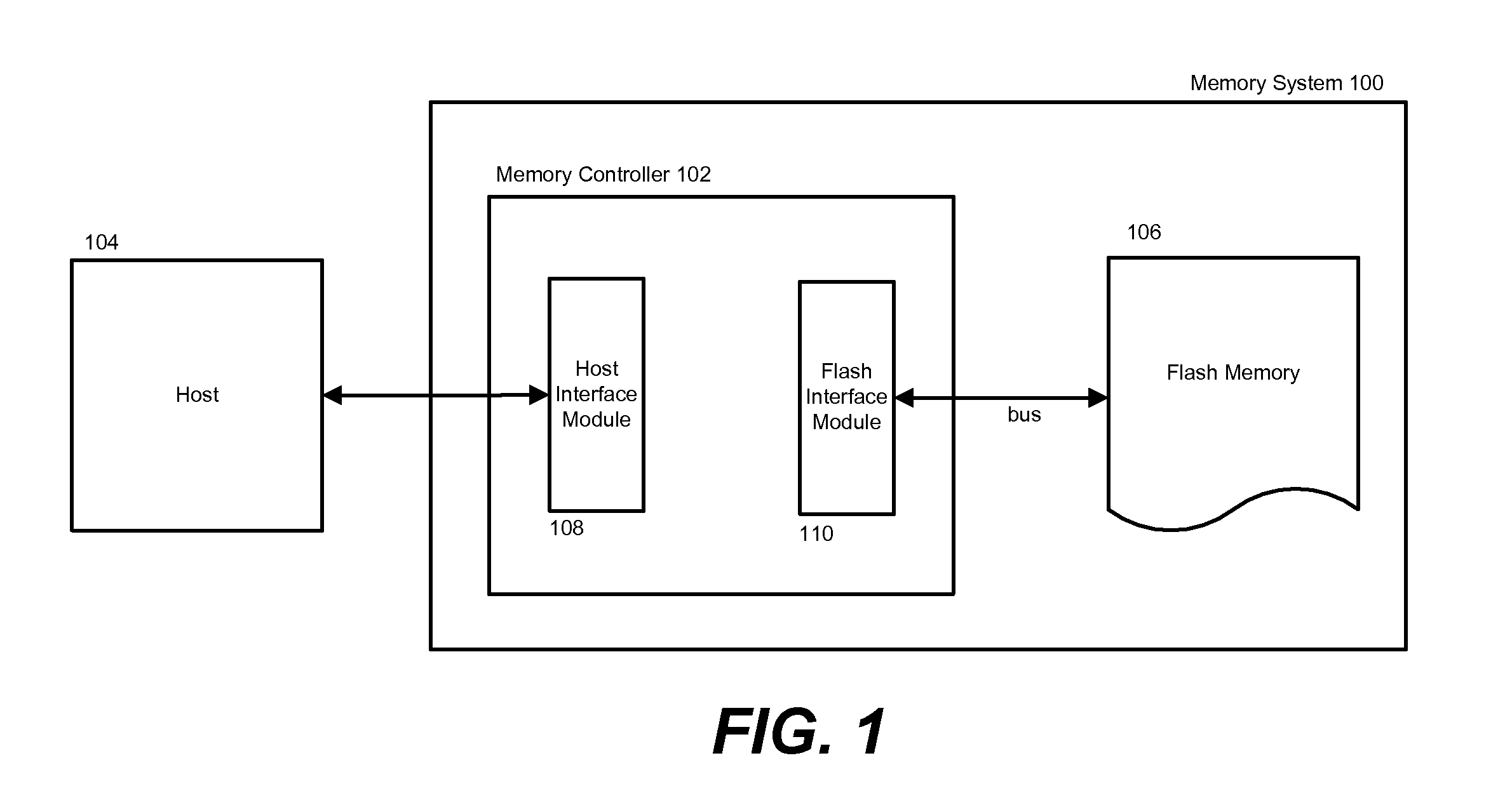
[0013]FIG. 1 illustrates an exemplary non-volatile memory system 100. Other memory systems may also be used according to embodiments of the present invention, and the present invention is not limited to nonvolatile memory systems, or any other particular memory system. FIG. 1 shows a memory controller 102 that includes flash memory 106 and interfaces with a host 104, which is for example a digital camera, laptop computer, MP3 player, PDA, or other similar electronic device.

[0014]Memory system products, such as nonvolatile memory system 100, are often categorized by performance grades. For example, each line of memory card products is often offered in several different speeds for each memory card size. Memory transfer speeds are generally specified in both kilobytes per second (KB / s) and megabytes per second (MB / s). Sometimes, transfer speeds are also specified with an “×” rating system similar to that of CD-ROMS. The “×” is a reference to the minimum CD-ROM speed of 150 KB / s. Thus, ...


PUM


Abstract

In order to maintain a memory system's performance levels to its end-of-life, latency threshold level(s) are specified and associated with different memory system operating parameters. In one embodiment, the memory system monitors and gathers performance statistics in real time, and in accordance with specific memory transfer sizes. A current latency level can be dynamically calculated using the performance statistics and compared to previously established latency threshold levels. If the current latency level is greater than or equal to a specific latency threshold level, the memory system's configuration setting can be adjusted according to the operating parameters associated with the latency threshold level to offset the increased latency.

Description

BACKGROUND OF THE INVENTION[0001]This invention relates to methods for maintaining the performance of memory systems until end-of-life, in particular nonvolatile memory systems that include a memory controller.[0002]Memory systems generally include multiple components which are in communication with each other and perform different functions as part of an overall system. One example of such a memory system is a nonvolatile memory system. Nonvolatile memory systems are used in various applications. Some nonvolatile memory systems are embedded in a larger system such as a personal computer. Other nonvolatile memory systems are removably connected to a host system and may be interchanged between different host systems. Examples of such removable memory systems (removable memory units) include memory cards and USB flash drives. Electronic circuit cards, including non-volatile memory cards, have been commercially implemented according to a number of well-known standards. Memory cards are...

Claims


Application Information

Patent Timeline
IPC IPC(8): G06F12/00
CPCG06F11/3419G06F11/3433G06F2201/81G06F11/3452
Inventor CHENG, STEVEN S.TAM, STEPHEN
Owner SANDISK TECH LLC
Learn More