Valve Gear of Internal Combustion Engine

a technology of internal combustion engine and valve gear, which is applied in the direction of non-mechanical valves, machines/engines, electrical control, etc., can solve the problems of deteriorating driveability, changing the rotary torque, and affecting the operation of the internal combustion engine, so as to achieve the effect of leveling the torqu

Inactive Publication Date: 2009-11-12
TOYOTA JIDOSHA KK
View PDF1 Cites 31 Cited by
  • Summary
  • Abstract
  • Description
  • Claims
  • Application Information

AI Technical Summary

Benefits of technology

[0034]In the inline four-cylinder internal combustion engine, the explosion stroke for the first cylinder is performed before the explosion stroke for the third cylinder. Therefore, a relative increase in the intake air amount for the first cylinder makes it possible to level the torque even when the combustion of the third cylinder is stopped.

Problems solved by technology

However, if the above technology, which uses electric motors to drive the intake valve and exhaust valve for each cylinder, is employed, it is anticipated that, for example, the electric motors or sensors for detecting the rotational position of the electric motors may become faulty.
If an internal combustion engine is continuously operated by using normal cylinders only, the explosion stroke becomes irregular, thereby changing the rotary torque.
This causes deteriorated driveability or makes it difficult to continue operating the internal combustion engine.

Method used


Image

  • Valve Gear of Internal Combustion Engine
  • Valve Gear of Internal Combustion Engine
  • Valve Gear of Internal Combustion Engine

Examples


first embodiment

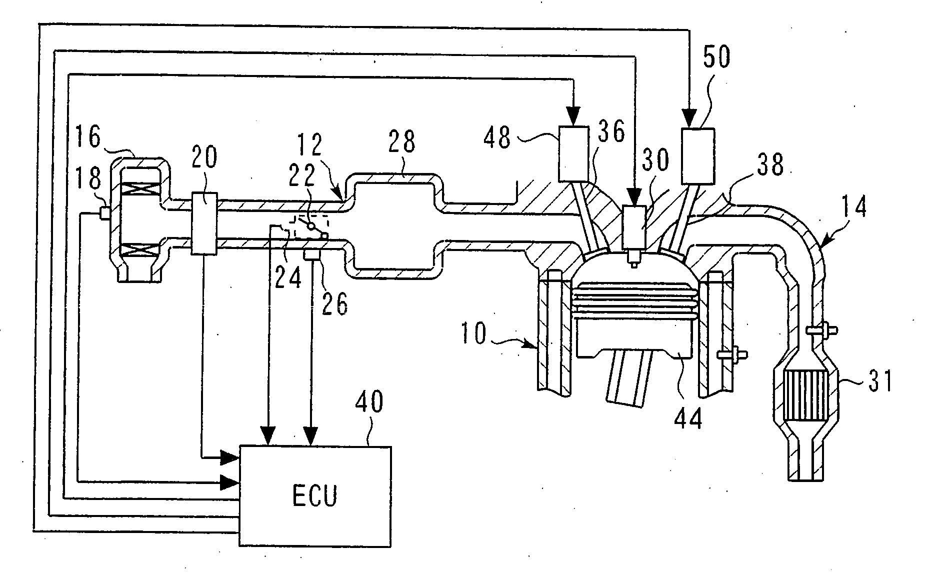
[0048]FIG. 1 is a schematic diagram illustrating the configuration of a system that includes a valve train for an internal combustion engine according to the preferred embodiments of the present invention. An internal combustion engine 10 communicates with an intake path 12 and an exhaust path 14. The intake path 12 is provided with an air filter 16, which is positioned at an upstream end. The air filter 16 includes an intake air temperature sensor 18, which detects intake air temperature THA (i.e., outside air temperature). The exhaust path 14 is provided with an exhaust purification catalyst 32.

[0049]An air flow meter 20 is positioned downstream of the air filter 16. A throttle valve 22 is positioned downstream of the air flow meter 20. A throttle sensor 24 and an idle switch 26 are positioned near the throttle valve 22. The throttle sensor 24 detects the throttle opening TA. The idle switch 26 turns on when the throttle valve 22 is fully closed. A surge tank 28 is positioned down...

second embodiment

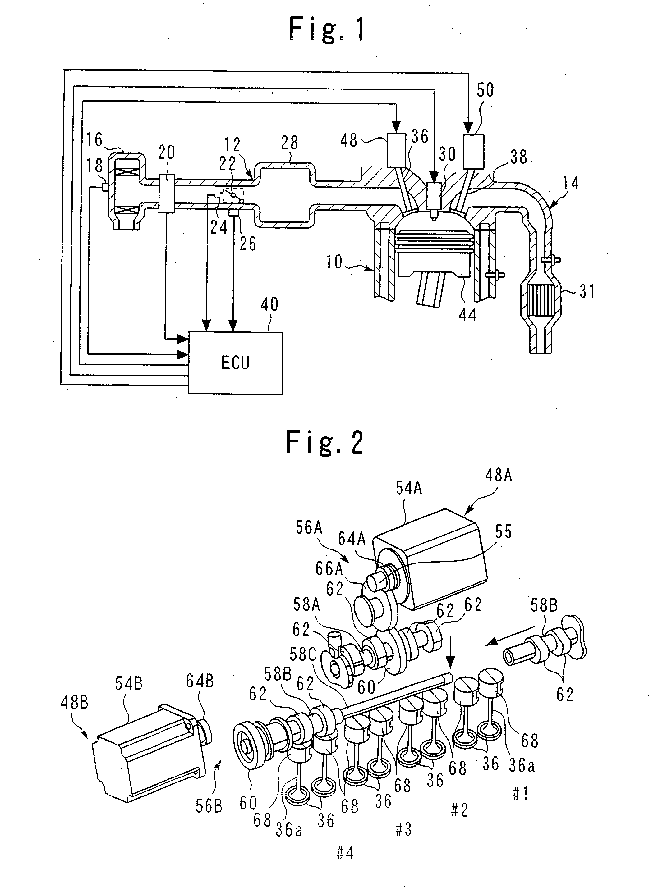
[0083]A second embodiment of the present invention will now be described. The second embodiment is such that the present invention is applied to a six-cylinder internal combustion engine 10. FIG. 7 is a schematic diagram illustrating the configuration of a section around valve trains 48, 50 according to the second embodiment. It mainly illustrates the configuration of a section around a cylinder head. The internal combustion engine 10 according to the present embodiment is a V-type six-cylinder engine. Cylinders #1, #3, and #5 are positioned in a bank 70, and the remaining three cylinders (cylinders #2, #4, and #6) are positioned in another bank 72.

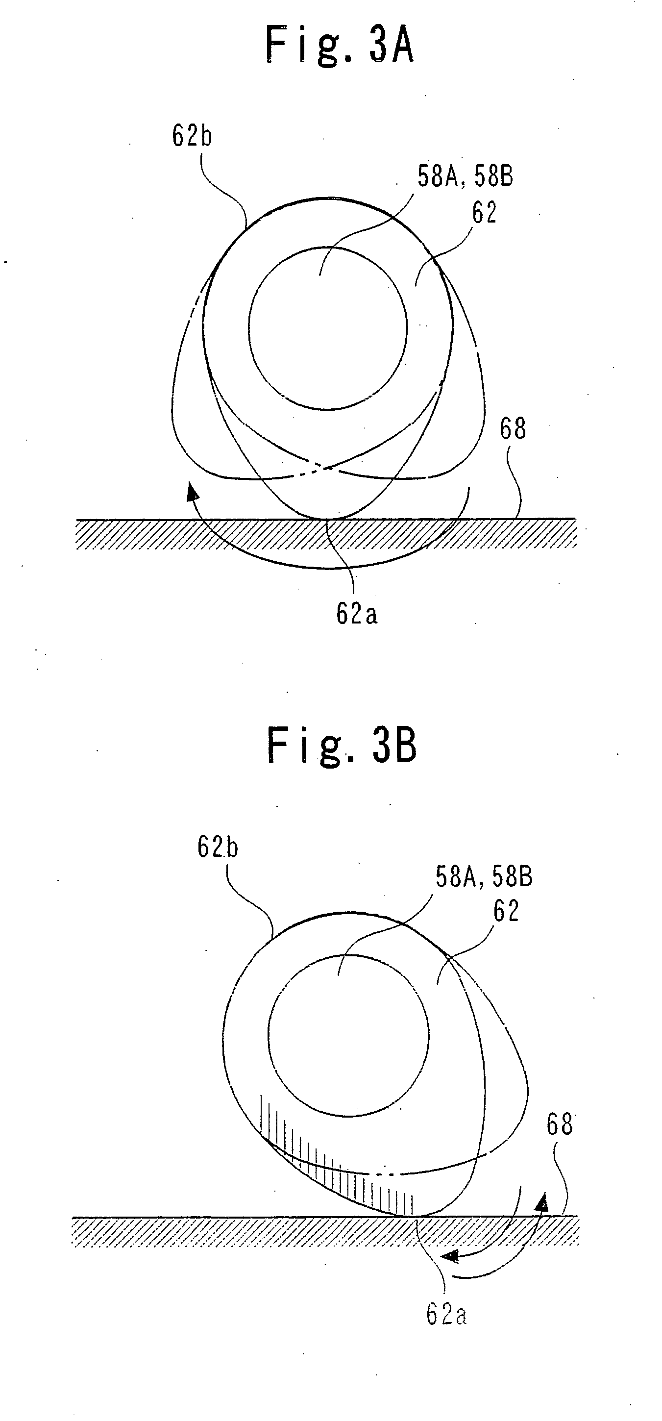
[0084]The banks 70, 72 both include a valve train 48 that drives intake valves 36, and a valve train 50 that drives exhaust valves 38. Here, although the configuration of the valve train 48 is mainly described, the valve train 50 has basically the same configuration as the valve train 48. Here it is assumed that each cylinder of the inter...

third embodiment

[0107]A third embodiment of the present invention will now be described. The third embodiment is such that the present invention is applied to an eight-cylinder internal combustion engine 10. FIG. 10 is a schematic diagram illustrating the configuration of a section around valve trains 48, 50 according to the third embodiment. It mainly illustrates the configuration of a section around a cylinder head. The internal combustion engine 10 according to the present embodiment is a V-type eight-cylinder engine. Cylinders #2, #4, #6 and #8 are positioned in a bank 80, and the remaining four cylinders (cylinders #1, #3, #5 and #7) are positioned in another bank 82.

[0108]The banks 80, 82 both include a valve train 48 that drives intake valves 36, and a valve train 50 that drives exhaust valves 38. Here, although the configuration of the valve train 48 is mainly described, the valve train 50 has basically the same configuration as the valve train 48. Here it is assumed that each cylinder of t...


PUM


Abstract

A valve train for an internal combustion engine that uses motors to open/close intake valves of cylinders. The motors drive the intake valves for each of a plurality of groups of cylinders that perform an explosion stroke at substantially equal crank angle intervals. Since the intake valves are driven for each of the plurality of groups of cylinders that perform an explosion stroke at substantially equal crank angle intervals, the explosion stroke is performed regularly even when an operation is conducted with only a particular group of cylinders. This makes it possible to inhibit driveability deterioration.

Description

TECHNICAL FIELD[0001]The present invention relates to a valve train for an internal combustion engine.BACKGROUND ART[0002]A known technology described, for instance, in JP-A No. 183610 / 2004, uses electric motors to drive an intake valve and exhaust valve for each cylinder.[0003]However, if the above technology, which uses electric motors to drive the intake valve and exhaust valve for each cylinder, is employed, it is anticipated that, for example, the electric motors or sensors for detecting the rotational position of the electric motors may become faulty. If an internal combustion engine is continuously operated by using normal cylinders only, the explosion stroke becomes irregular, thereby changing the rotary torque. This causes deteriorated driveability or makes it difficult to continue operating the internal combustion engine.[0004]The present invention has been made to solve the above problem. It is an object of the present invention to carry out the explosion stroke regularly...

Claims


Application Information

Patent Timeline
Patent Type & Authority Applications(United States)
IPC IPC(8): F01L1/34F02D17/02F01L9/20F01L9/22
CPCF01L1/024Y02T10/18F01L1/344F01L9/04F01L13/0005F01L13/0015F01L2001/028F01L2001/0476F01L2001/0537F01L2009/0411F01L2009/0421F01L2800/08F01L2820/032F02D13/06F02D17/02F02D41/0082F02D41/0085F02D2041/0012F01L1/042Y02T10/12F01L2009/25F01L9/22F01L9/20
Inventor EZAKI, SHUICHI
Owner TOYOTA JIDOSHA KK
Why Eureka
Try Eureka