Charcoal Starting Device and Method

a starting device and charcoal technology, applied in the direction of firelighters, household stoves or ranges, solid fuels, etc., can solve the problems of inability to guarantee rapid coal formation, poor combustion effect, and general dusty charcoal, and achieve the effect of facilitating air ingress

Inactive Publication Date: 2009-11-12
GREIF PACKAGING
View PDF34 Cites 26 Cited by
  • Summary
  • Abstract
  • Description
  • Claims
  • Application Information

AI Technical Summary

Benefits of technology

[0006]Another embodiment of the invention relates to an improved charcoal igniting device. The improved charcoal igniting device includes a container, chimney, and base. The container has a container sidewall, an upper container rim, and a lower container rim. The chimney is disposed co-axially within the container. The chimney has a chimney sidewall, an upper chimney rim, and a lower chimney rim. The base is defined by an outer base perimeter mated to the lower container rim and a centrally located orifice having an edge mated to the lower chimney rim. A container volume is defined by the container sidewall, the base, and an exterior surface of the cone sidewall. The improvements of the charcoal igniting device include a series of holes defined by the container sidewall to facilitate an ingress of air therein. The chimney is an n-faceted frustum and a plurality of tabs and corresponding mating slots are included to retain an assembled shape of the container and chimney. In addition, the improved charcoal igniting device includes a supply of wax impregnated in the chimney sidewall to provide a fuel to ignite the supply of charcoal and an ignition element disposed on the upper chimney rim. In response to ignition of the ignition element, the wax impregnated chimney sidewall burns and draws air upwardly through the chimney and inwardly and upwardly through the series of holes in the container sidewall, and a flame front proceeds in an inverted cone downwardly through the container volume.

Problems solved by technology

However, even with these accelerants, rapid coal formation is not guaranteed.
Unfortunately, charcoal is generally dusty and this very dark or black dust may be messy or otherwise objectionable to some individuals.

Method used


Image

  • Charcoal Starting Device and Method
  • Charcoal Starting Device and Method
  • Charcoal Starting Device and Method

Examples


Embodiment Construction

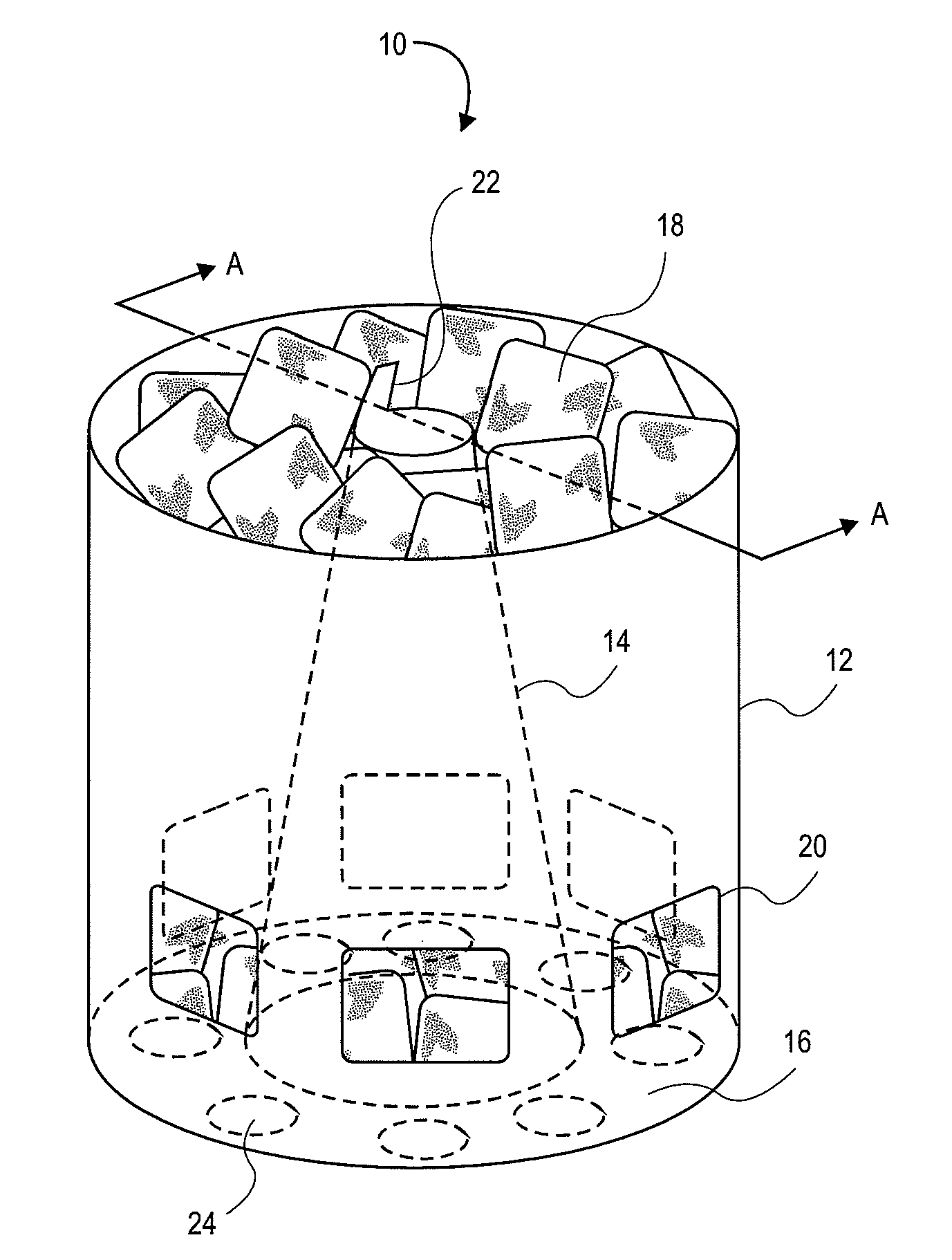
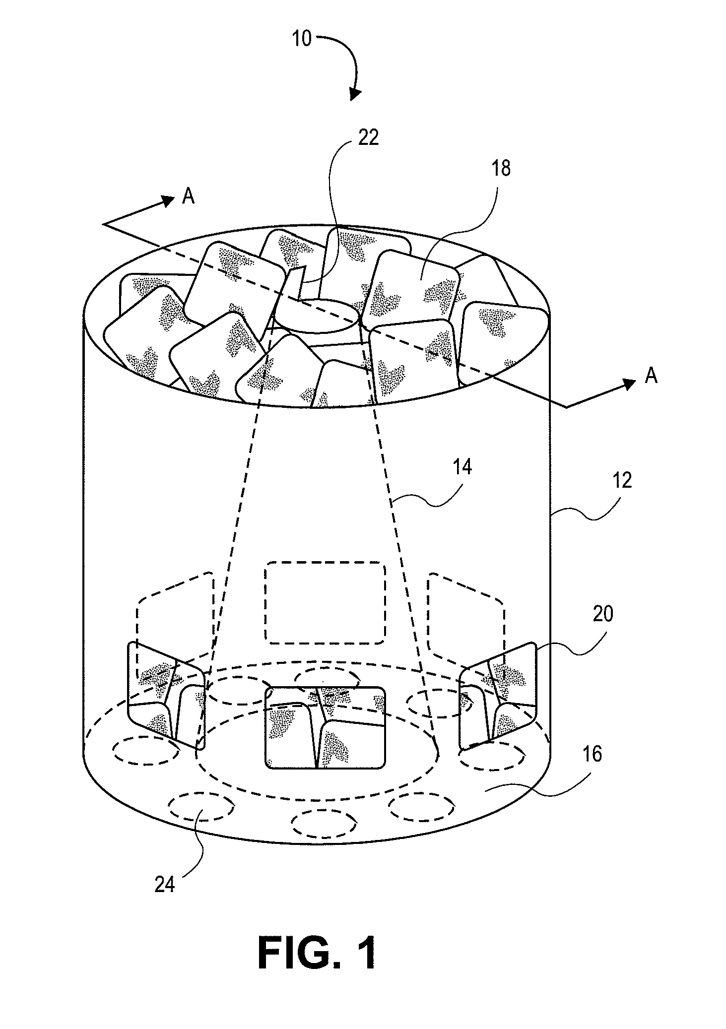
[0018]The present invention provides, in some embodiments, a charcoal starting or igniting device and a method of fabricating the charcoal igniting device. In general, the charcoal igniting device includes an envelope or container configured to retain a supply of charcoal. For the purpose of this disclosure, an envelope is defined as a structure to enclose or partially enclose a space, volume, or item. This envelope includes a fiber-based sheet stock such as, for example, fiberboard, corrugated fiberboard, and the like. For the purpose of this disclosure, the term, “fiberboard” is defined as at least including, for example, paper, paperboard, cardboard, corrugated cardboard, cellulosic, and / or resinous material which is similar in character to fiberboard, and which is manipulated in the same or similar manner as fiberboard. This includes any suitable material capable of being folded from a blank. In this regard, the term “blank” refers to at least a piece or unit of fiberboard that ...


PUM

PropertyMeasurementUnit
heightaaaaaaaaaa
widthaaaaaaaaaa
volumeaaaaaaaaaa

Abstract

A charcoal igniting device includes an envelope, a chimney, and a base. The envelope has an envelope height and an envelope width, the envelope height is greater than the envelope width. The envelope sidewall defines a series of holes. The envelope has an upper envelope rim and a lower envelope rim. The chimney is disposed co-axially within the envelope. The chimney has a sidewall impregnated with wax, an upper chimney rim, an ignition element disposed upon the upper chimney rim, and a lower chimney rim. The base defines a series of holes disposed through the base. The base has an outer base perimeter mated to the lower envelope rim and an inner base perimeter mated to the lower chimney rim.

Description

CROSS REFERENCE TO RELATED APPLICATIONS[0001]This application is a Continuation-In-Part Application and claims priority to U.S. patent application Ser. No. 12 / 117,481, filed on May 8, 2008, titled “CHARCOAL STARTING DEVICE AND METHOD”, the disclosure of which is incorporated herein by reference in its entirety.FIELD OF THE INVENTION[0002]The present invention generally relates to a charcoal ignition device. More particularly, the present invention pertains to a device for storing and ignition of charcoal and a method of fabricating the device.BACKGROUND OF THE INVENTION[0003]It is generally known that charcoal is utilized as a fuel source for cooking or grilling foodstuffs. Typically, a supply of charcoal is placed on a grating of a grill and ignited. Once the charcoal has formed uniformly alighted coals, the foodstuffs may be grilled. To accelerate ignition, conventional charcoal may include various flammable waxes and / or petroleum distillates. However, even with these accelerants,...

Claims


Application Information

Patent Timeline
Patent Type & Authority Applications(United States)
IPC IPC(8): C10L11/00
CPCC10L11/02C10L5/36C10L5/368Y10T29/49
Inventor FISCHER, DAVID B.APOSTOLUK, PETER R.LALLATHIN, JAMES E.
Owner GREIF PACKAGING
Why Eureka
Try Eureka