Rotation damper

a damper and rotational technology, applied in the direction of liquid based dampers, liquid resistance brakes, brake types, etc., can solve the problem of peculiar sound generation, reduce the influence of generated torque at the resistance member, suppress the influence of generated torque, and reduce the irregularity of generated torqu

Inactive Publication Date: 2009-11-12
NIFCO INC
View PDF6 Cites 13 Cited by
  • Summary
  • Abstract
  • Description
  • Claims
  • Application Information

AI Technical Summary

Benefits of technology

[0025]Also, because the air stopping member of the housing is provided in a place that does not face the resistance member, the influence on the torque generated at the resistance member can be reduced.
[0026]Also, because there is provided a spacer which partitions between the air stopping member of the housing and the resistance member, irregularity of the generated torque can be reduced by partitioning the air in the air stopping member from the resistance member by the spacer.
[0027]Also, in a rotary damper having a viscous fluid inside a housing, because the generated torque also becomes greater as the rotational speed becomes faster, the main torque is generated in the vicinity of the outermost periphery of the resistance member, therefore, by providing the air stopping member of the housing in a portion other than a portion corresponding to the vicinity of the outermost periphery of the resistance member, the influence on the generated torque can be suppressed.
[0028]Also, because the plurality of divided air stopping members in the resistance member serves as pass-through holes, and the passages for air movement which connect the pass-through holes serve as recessed grooves provided on the housing, the air incorporated into the housing during assembly can move from one pass-through hole to another pass-through hole via the recessed groove in a state being not excessively compressed.
[0029]Accordingly, even though the rotor rotates in both directions, because the air stopped in the pass-through hole moves from one pass-through hole to another pass-through hole via the recessed groove in a state being not excessively compressed, the generation of a peculiar sound due to the air incorporated into the housing can be prevented.
[0030]Furthermore, because the pass-through holes are provided concentrically, and the recessed grooves are circumferential grooves provided on the housing corresponding to the pass-through holes, the air incorporated into the housing during assembly can be made to move from one pass-through hole to another pass-through hole in a state further being not compressed, whereby a peculiar sound due to the air incorporated into the housing can be further prevented.

Problems solved by technology

However, because the rotor rotates in both directions, a peculiar sound is generated when the air incorporated into the housing crosses over the resistance member and moves to the opposite side of the resistance member.

Method used


Image

  • Rotation damper
  • Rotation damper
  • Rotation damper

Examples


second embodiment

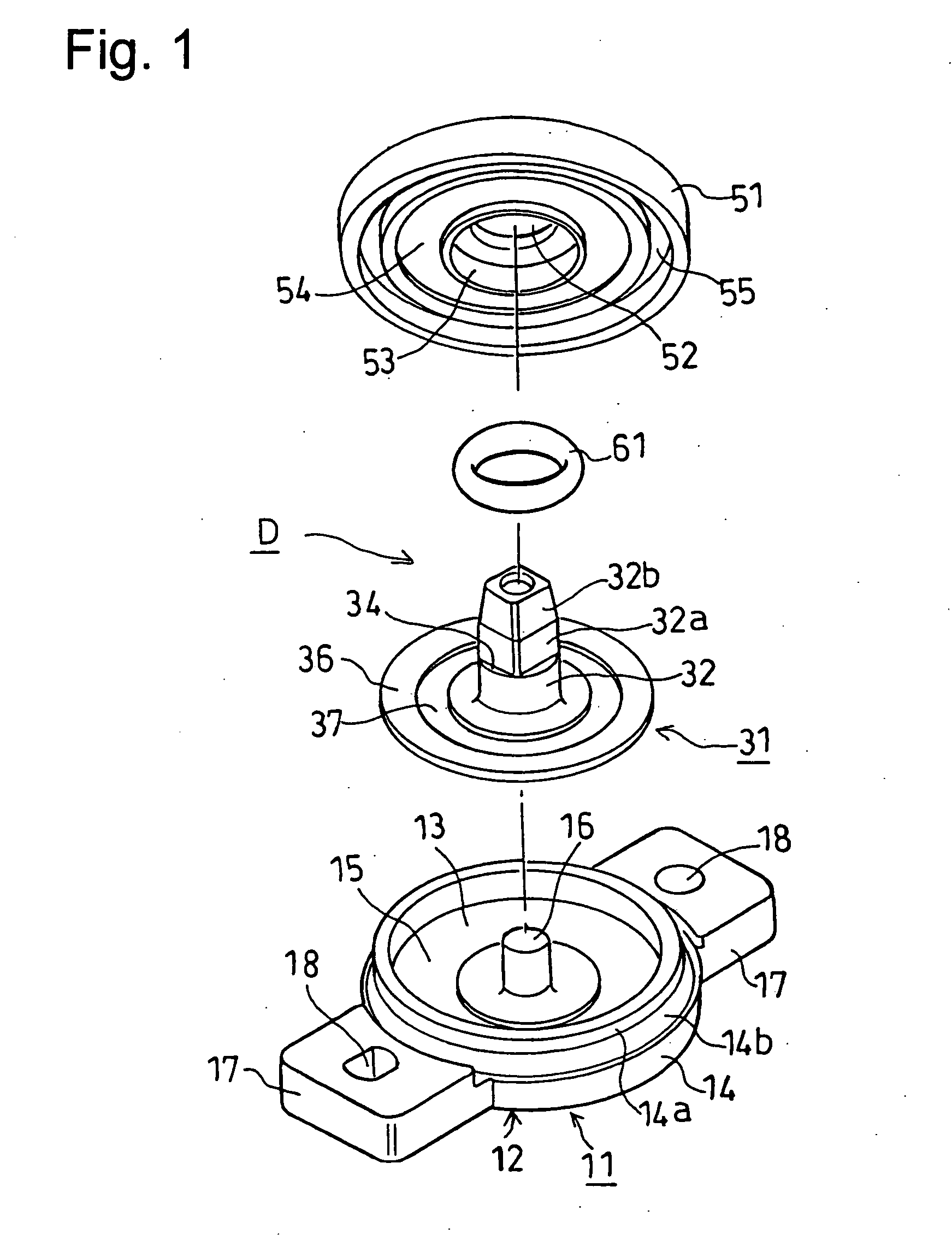
[0089]FIG. 10 is an exploded perspective view showing the rotary damper of this invention, the same symbols are assigned to the same or similar parts as in FIGS. 1-9, and the explanation is omitted.

first embodiment

[0090]Also, the parts omitted in illustration are constituted in the same manner as in the

[0091]In FIG. 10, on the inside bottom face of the bottom part 13, a circumferential groove 13a is provided on a concentric circle centered on the center of the shaft bearing part 16 as an air stopping member.

[0092]Also, because the method of assembly of the rotary damper D is the same as the first embodiment, the explanation is omitted.

[0093]By this embodiment, because a circumferential groove 13a is provided on the inner face of the bottom part 13 of the case 11 constituting the housing facing the resistance member 36, and a circumferential groove 54 is provided on the inner face of the cap 51 constituting the housing facing the resistance member 36, the air incorporated into the housing during assembly can be stopped in these circumferential grooves 13a, 54.

[0094]Accordingly, even though the rotor 31 rotates in both directions, the air stopped in the circumferential grooves 13a, 54 moves ins...

third embodiment

[0099]FIG. 11 is an exploded perspective view showing the rotary damper of this invention, the same symbols are assigned to the same or similar parts as in FIGS. 1-10, and their explanation is omitted.

[0100]Also, the parts omitted in illustration are constituted in the same manner as in the first embodiment.

[0101]In FIG. 11, on the cap 51, plural, for example, three divided arc-shaped grooves 54A are provided as divided air stopping members constituting an air stopping member, on concentric circles centered on the center of the pass-through hole 52, on the outside of the ring-shape step part 53 on the lower-side and the inside of the coupling recessed groove 55.

[0102]Also, because the method of assembly of the rotary damper D is the same as the first embodiment, the explanation is omitted.

[0103]By this embodiment, because a plurality of divided arc-shaped grooves 54A are provided on the inner face of the cap 51 constituting the housing facing the resistance member 36, the air incorp...


PUM


Abstract

A rotary damper is provided so that air incorporated into a housing during assembly is, not excessively compressed, whereby a generation of a peculiar sound due to the air incorporated into the housing can be prevented even though the rotor rotates in both directions, and so that the air is stopped and captured in a fixed place whereby influence on the generated torque can be reduced, and irregularity of the torque can be reduced progressively.
A rotary damper includes a housing (11, 51), silicon oil housed inside the housing (11, 51), a rotor 31 housed inside the housing (11, 51), and having a shaft member (32) projecting from the housing (11, 51) and having a resistance member (36) moving through the silicon oil (21) inside the housing (11, 51), and an O-ring (61) for preventing leakage of the silicon oil (21) from between the shaft member (32) and the housing (51). A circumferential groove (54) is provided on an inner face of the housing (51) facing the resistance member (36).

Description

TECHNOLOGICAL FIELD[0001]This invention relates to a rotary damper, for example, for damping the rotation of a driving gear which engages with a gear or a rack.BACKGROUND ART[0002]The above-mentioned rotary damper comprises a housing, a viscous fluid enclosed in this housing, a rotor provided inside the housing and having a resistance member, which moves through the viscous fluid inside the housing, provided on a shaft member partially protruding out from the housing, and seal member for preventing leakage of the viscous fluid from between the shaft member of the rotor and the housing.[0003]Furthermore, a driving gear is attached on the shaft member projecting out from the housing (for example, Japanese Patent Publication No. H4-34015).DISCLOSURE OF THE INVENTION[0004]In the conventional rotary damper, the shape of the resistance member is made roughly oval so that air incorporated into the housing during assembly is not allowed to be positioned between the resistance member as the ...

Claims


Application Information

Patent Timeline
Patent Type & Authority Applications(United States)
IPC IPC(8): F16F9/12
CPCF16F9/12F16F9/10
Inventor YAMAGUCHI, KEIJIJINBO, NAOTOTOMITA, SHIGEMITSUOKABAYASHI, SYUNSUKEKITAKAWA, AYAKOTOU, BUNKINHIRANO, YUKIKOIZUMI, KAZUYOSHITAKEI, YOSHIHISA
Owner NIFCO INC
Why Eureka
Try Eureka