Used oil container

a technology for oil containers and containers, applied in the direction of tray containers, transportation and packaging, mechanical equipment, etc., can solve the problems of reducing engine efficiency and engine life, increasing the potential for wear, and reducing the lubricity, so as to achieve a wider base and greater length and width

Inactive Publication Date: 2009-11-12
WEINBERGER GRP THE
View PDF12 Cites 3 Cited by
  • Summary
  • Abstract
  • Description
  • Claims
  • Application Information

AI Technical Summary

Benefits of technology

[0011]Similarly, the dimensions of the container are a matter of design choice. However, it is preferred that the container have a larger base, i.e., greater length and width than height, so as to be more stable when the container filled with used oil is placed in the trunk of a car, etc., for transport to the reclamation facility. Additionally, it is intended that the unused container be stackable, to aid in the shipment, storage and display of the item prior to sale.

Problems solved by technology

However, oil used in engines tends to break down with use over a period of time, such that the lubricity is reduced and the potential for wear increases.
Additionally, oil picks up particulate contaminates caused by engine wear that can score engine parts, also reducing engine efficiency and engine life.
Due to the severe environmental impact when improperly disposed of, recycling of used motor oil has become required by law throughout the United States and abroad.
This requires the user to drain the used oil into a collection pan and then transfer the used oil from the collection pan into the fluid container, risking spillage.
Not only is this inconvenient for the user, to first collect the oil in a collection pan and then transfer it into a fluid container, but having to stop the transfer when a first fluid container is full and resume the transfer to a second container creates potential problems in knowing when the first container is full and spillage as flow from the pan is stopped when changing fluid containers.

Method used


Image

  • Used oil container
  • Used oil container
  • Used oil container

Examples


Embodiment Construction

[0026]The following description is directed to a preferred embodiment of the present invention and is provided to better understand the invention without limiting the scope of the invention in any manner whatsoever.

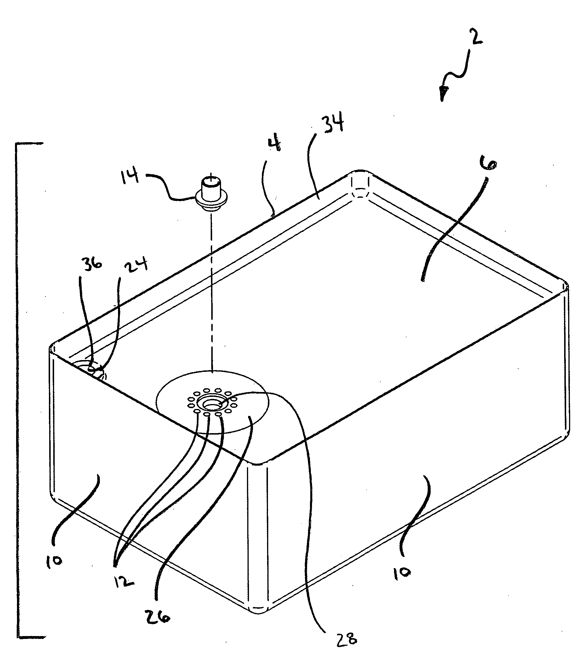
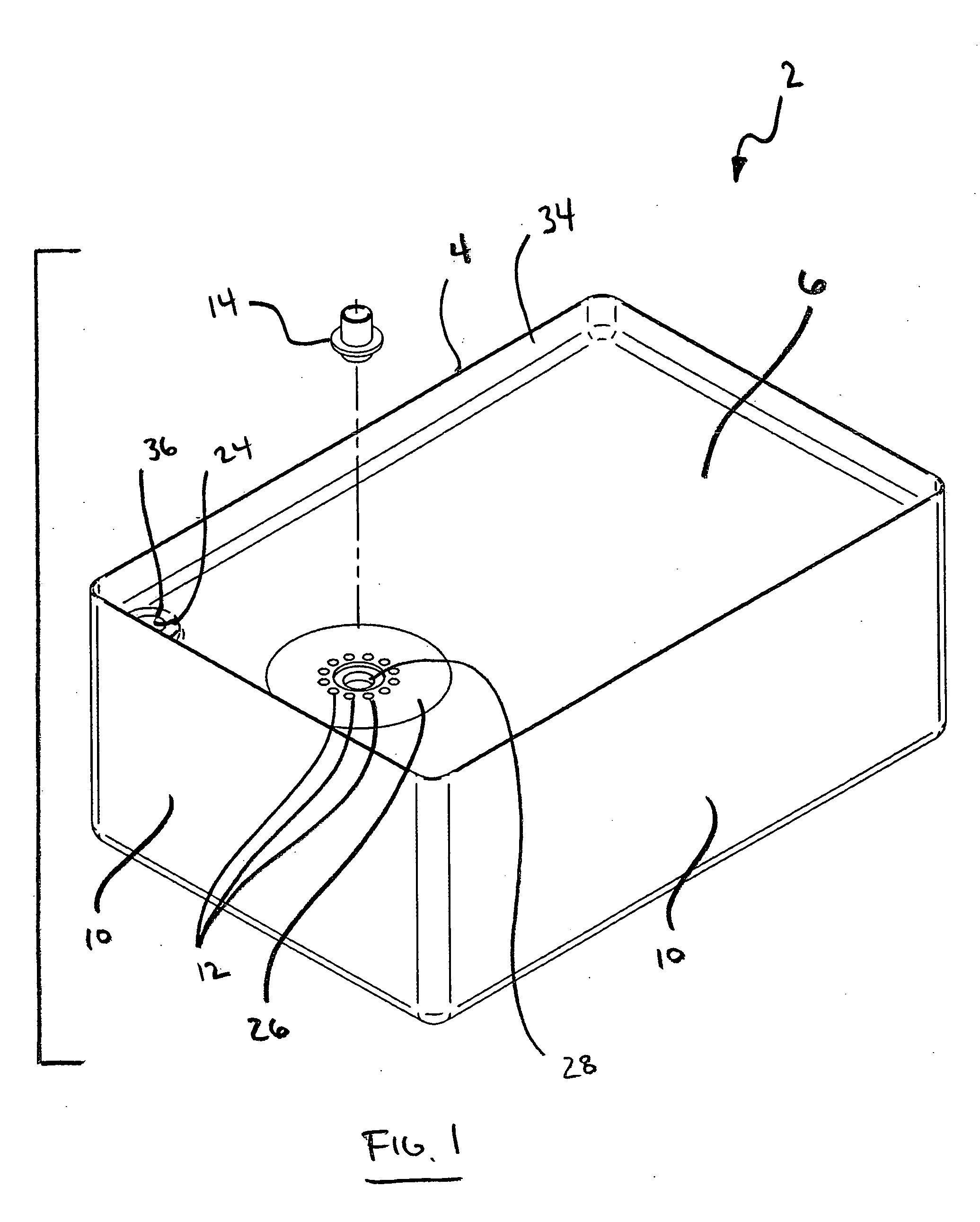
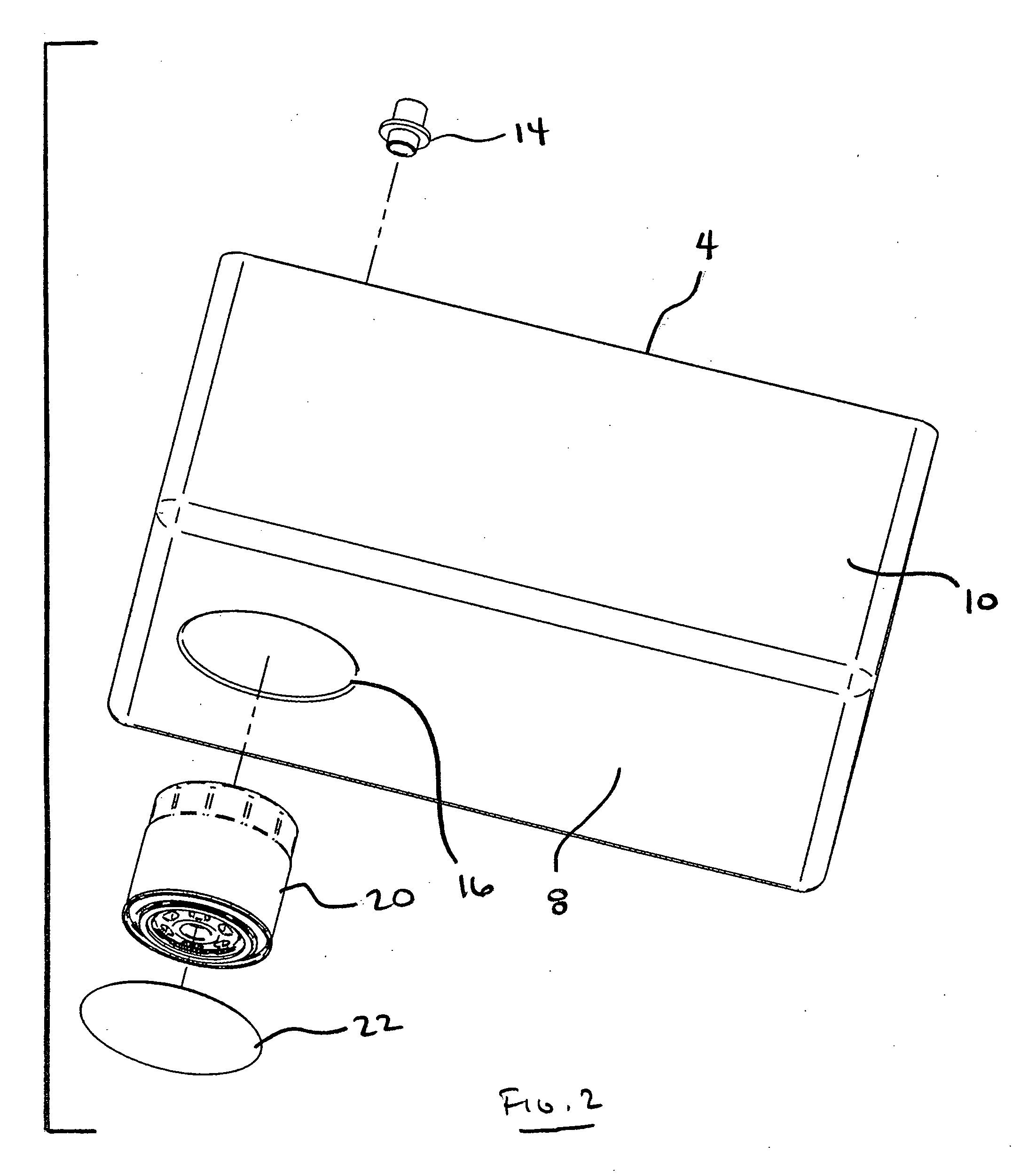
[0027]As shown in the drawings, and each of FIGS. 1-4, the present invention is directed to a used oil container 2 comprising a sealable container body 4 having a top 6, a bottom 8 and sides 10. The top 6 has a sloping configuration toward one or more openings 12 through which the used oil can enter the container 2. A threaded shaft 14 is adapted to extend from the top 6 of the container body 4 in the area of the one or more openings 12, and conforms to the threaded receiver on a used oil filter 18. Thus, once the used oil has been received into the container 2, the used oil filter can be screwed onto the threaded shaft 14 to seal the one or more openings 12 and allow the used oil from the used oil filter to also drain into the container 2 through the one or more openings...


PUM

PropertyMeasurementUnit
thicknessaaaaaaaaaa
volumeaaaaaaaaaa
thicknessaaaaaaaaaa

Abstract

A used oil container comprising a sealable container body having a top, a bottom and sides, the top having a sloping configuration toward one or more openings through which the used oil can enter the container, a threaded shaft adapted to extend from the top of the container body in the area of the one or more openings that conforms to the threaded receiver on a used oil filter, a compartment on one or more of the top, bottom or side of the container body adapted for accepting a new oil filter prior to use, wherein the treaded shaft is adapted to receive a used oil filter to seal the one or more openings of the container.

Description

FIELD OF THE INVENTION[0001]The present invention relates generally to the field of containers for fluids, and more particularly to containers for holding used motor oil for reclamation.BACKGROUND OF THE INVENTION[0002]Engines, as used in automobiles, trucks, boats, planes, power equipment and the like, require oil to lubricate moving parts. The oil is used to prevent excess wear, increase efficiency and increase engine life. However, oil used in engines tends to break down with use over a period of time, such that the lubricity is reduced and the potential for wear increases. Additionally, oil picks up particulate contaminates caused by engine wear that can score engine parts, also reducing engine efficiency and engine life. Therefore, the oil and oil filter must be changed regularly to keep an engine running well.[0003]The used oil removed from the vehicle is a hazardous waste that must be disposed of properly to protect the environment. Due to the severe environmental impact when...

Claims


Application Information

Patent Timeline
Patent Type & Authority Applications(United States)
IPC IPC(8): F16N31/02B65D79/00B65D85/00B65D69/00B65D1/36F16N33/00
CPCF16N31/006
Inventor SAWYER, GEORGE MCLUREWEINBERGER, JOSEPH
Owner WEINBERGER GRP THE
Why Eureka
Try Eureka