Cap Closure

a technology of cap closure and lid, which is applied in the direction of closure lids, containers, bottles, etc., can solve the problems of unsuitable use of plastic containers, unsuitable for liquid pouring, and unsuitable for torn foil edges within the spou

Inactive Publication Date: 2009-11-12
BAPCO CLOSURES RES
View PDF22 Cites 12 Cited by
  • Summary
  • Abstract
  • Description
  • Claims
  • Application Information

AI Technical Summary

Problems solved by technology

This assembly is not suitable for use with a plastics container where it would be impractical for the user to tear an opening in a plastics walled container.
This would not be a problem when the bottle is used for tablets or the like but a torn foil edge within the spout is unsuitable for the pouring of liquids.
Although these documents are referred to as the most relevant prior art they do not represent a natural starting point for those seeking to solve the technical problems described in relation to thin-walled plastics bottles, in which the teaching has hitherto been directed exclusively at integral formation of the bottle body and neck.
Therefore, although it is known to produce a separate component defining a neck as in GB-A-2 108 464, the possibility of using this approach to solve the long present technical problems of effective reclosable sealing of thin-walled blow moulded plastics containers for fluids had not hitherto been appreciated and cannot therefore be regarded as obvious.

Method used


Image

  • Cap Closure
  • Cap Closure
  • Cap Closure

Examples


Embodiment Construction

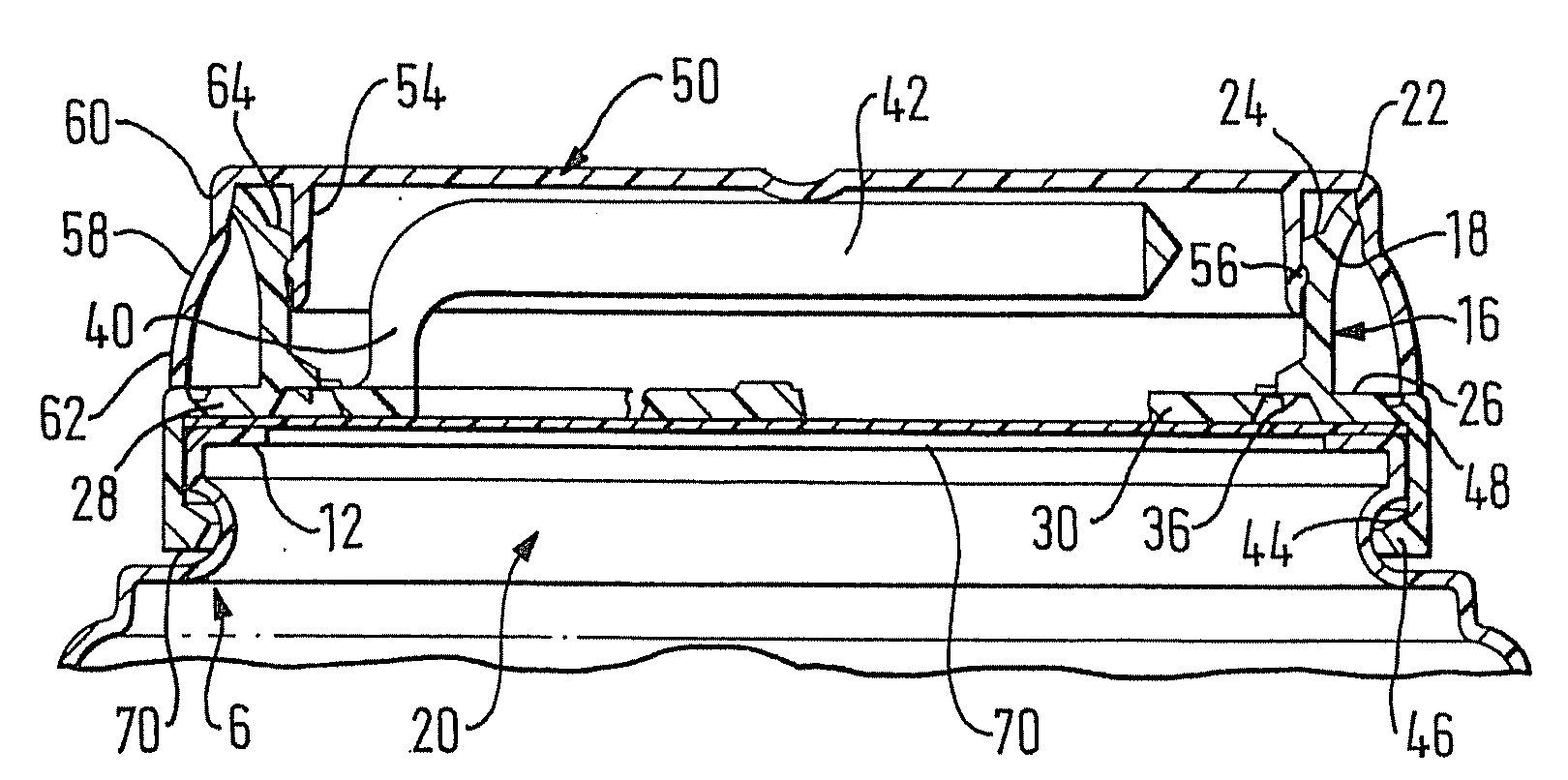
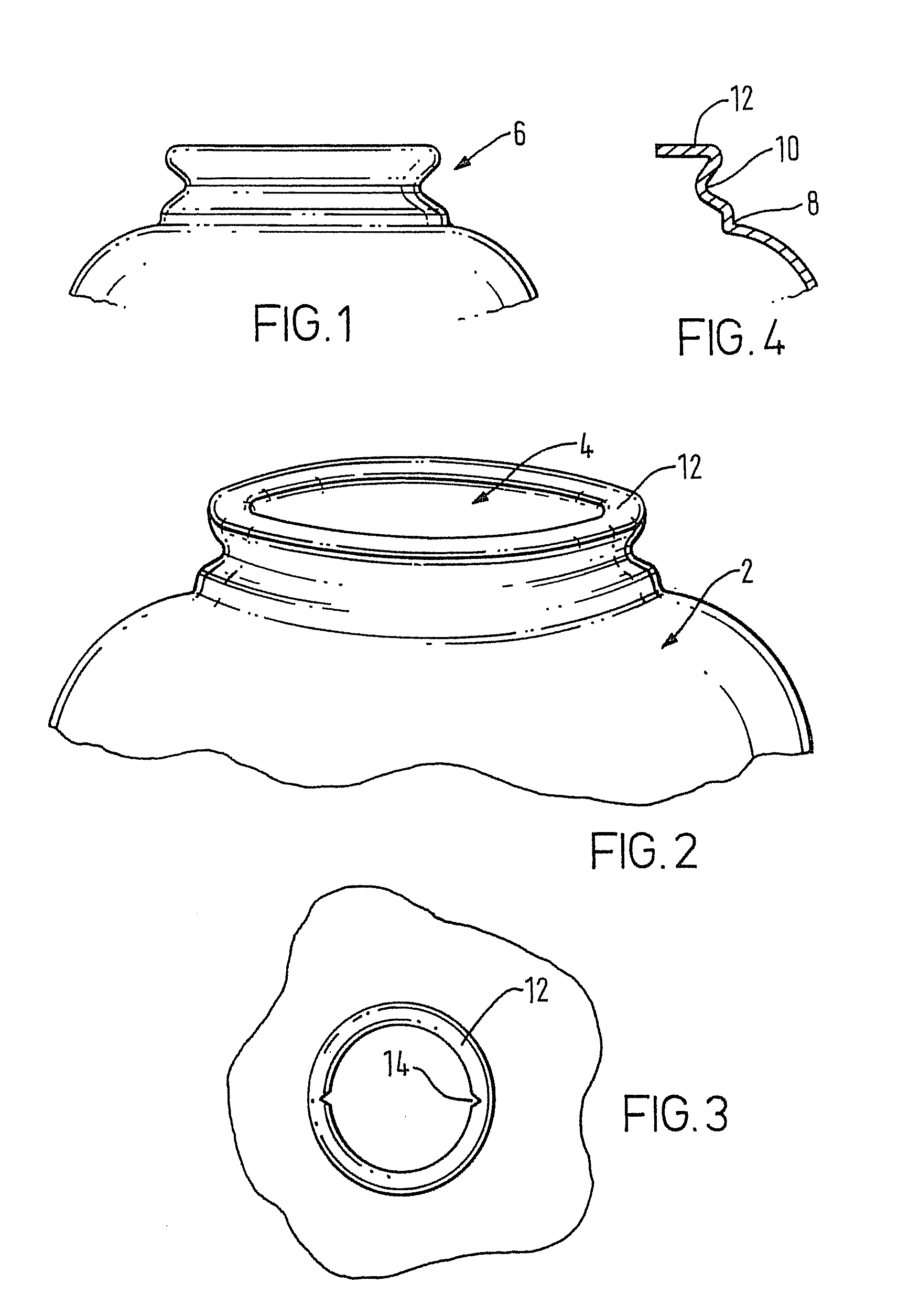
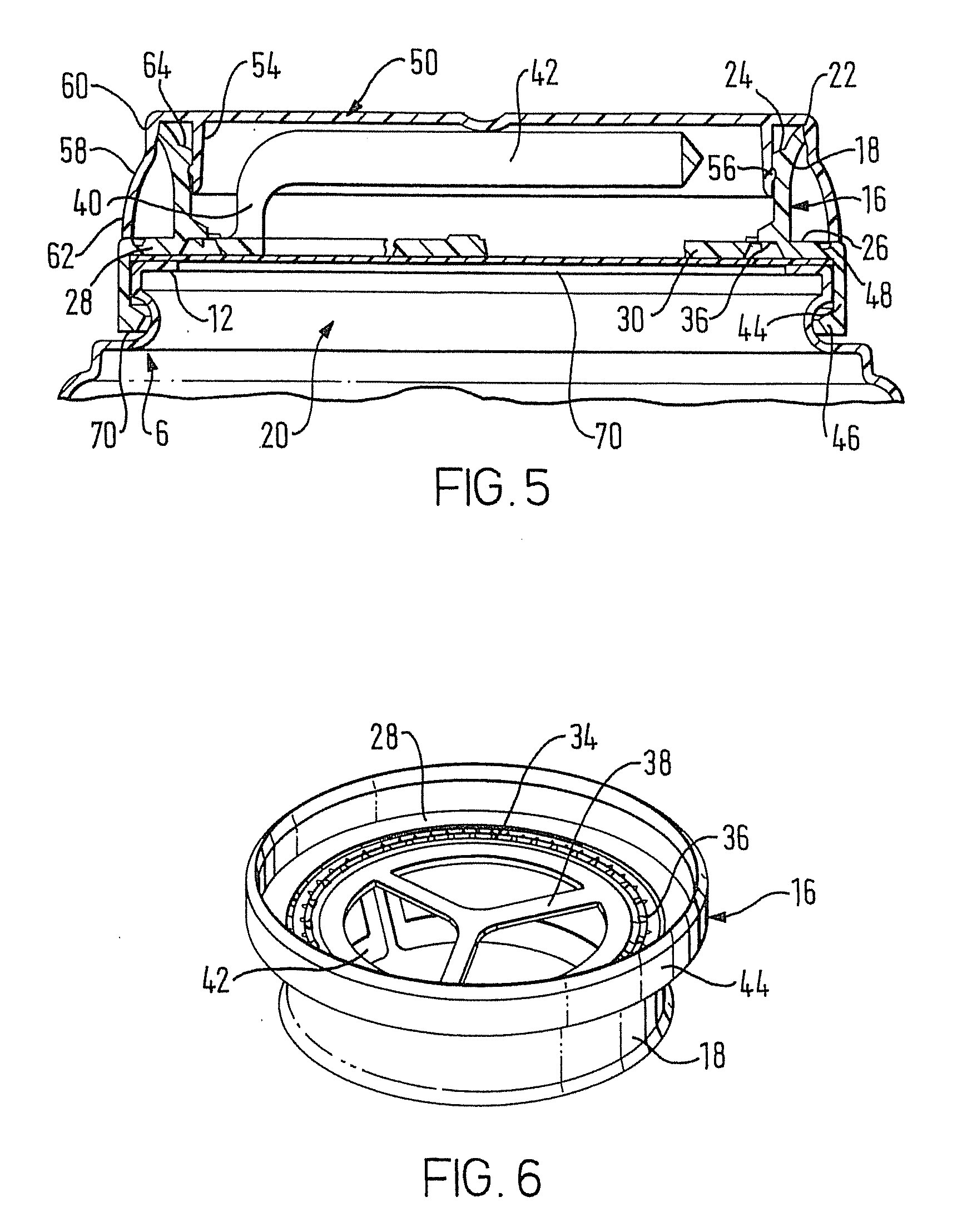
[0047]A bottle body 2 has a mouth 4, which is integrally formed in a single blow moulding operation. The remainder of the body shape has not been shown as it may take any suitable form. For example it may be square, rectangular or round in section and may have an integral handle formed as part of the body shape.

[0048]The profile 6 of the mouth is best shown in FIG. 4 and comprises a vertical wall 8 adjoining an indented recess 10 which merges into an inwardly directed horizontal seating flange 12. The purpose of the recess 10 is to give the mouth profile more rigidity and resistance to compression when top loaded during the subsequent operations to attach a neck and cap assembly. It is also used to locate a mouth of the neck assembly when applied in the filling process.

[0049]The body 2 with its shaped mouth profile 6 is formed by the mould against which a parison of high density polyethylene or other suitable plastics is inflated in any appropriate conventional extrusion blow mouldi...


PUM

PropertyMeasurementUnit
weightaaaaaaaaaa
thicknessesaaaaaaaaaa
weightaaaaaaaaaa

Abstract

A sealing arrangement for a plastic bottle includes a blow-molded bottle having a body and a mouth that includes an opening, an injection molded neck that includes a continuous wall that defines a top wall-opening and a bottom wall-opening. The top wall-opening provides a pour spout for liquid contained within the body of the bottle. The bottom wall-opening is fused to the mouth of the bottle so as to surround the bottle's opening. A removable flange is located generally within the bottom wall-opening and a frangible region connects the flange to the wall. A foil is secured to a side of the flange that is generally adjacent to the bottom wall-opening, and the foil is adapted to close the bottom wall-opening. A plurality of foil-cutting teeth are carried by the wall generally adjacent to the bottom wall-opening, generally adjacent to the side of the flange and generally adjacent to the foil. A pull member is secured to the flange. Manual operation of the pull member separates the flange from the wall, as at least a portion of the foil is cut by the teeth. An injection-molded cap removably closes the top wall-opening. The wall includes a weakened portion that will break upon an attempt to physically remove the wall from the bottle. The cap includes a cover plate that covers the top wall-opening and a skirt that extends from the cover plate to cover the weakened portion of the wall.

Description

REFERENCE TO RELATED APPLICATIONS[0001]This application is a divisional of U.S. patent application Ser. No. 09 / 701,057, filed Nov. 22, 2000; which is national stage application under 35 U.S.C. § 371 of International Application No. PCT / GB11999 / 01094, filed Apr. 9, 1999; which claims priority to International Application No. PCT / GB98 / 03433, filed Nov. 13, 1998 and GB 9811308.7 filed May 26, 1998, the entire disclosures of each of which are hereby incorporated by reference herein.BACKGROUND OF THE INVENTION[0002]The present invention relates to fluid packaging.[0003]The present invention particularly relates to packaging using thin-walled extrusion blow moulded plastics bottles for fluids such as milk, which require to be filled and closed in a resealable manner.[0004]The invention also relates to resealable cap closures for use with plastics bottles or composite material cans, and more specifically to such closures which provide tamper evidence.[0005]In the specification that follows...

Claims


Application Information

Patent Timeline
Patent Type & Authority Applications(United States)
IPC IPC(8): B65D41/00B65B3/02B65D1/02B65B7/28B65D17/28B65D17/30B65D43/02B65D47/10B65D47/36B65D51/20
CPCB65B3/022B65B7/2878B65D1/0238B65D47/103B65D51/20B65D2251/0015B65D2543/00796B65D2251/0056B65D2251/0087B65D2251/0093B65D2543/00629B65D2543/00685B65D2543/0074B65D2251/0018B65D43/021B65D2543/00518B65D2543/00537B65D2543/00555
Inventor VON SPRECKELSEN, HENNINGMCGEOUGH, PETER M.
Owner BAPCO CLOSURES RES
Why Eureka
Try Eureka