Method and Measuring Device for Radio Wave Measuring

a radio wave and measurement method technology, applied in the direction of material analysis, material analysis using microwave means, instruments, etc., can solve the problems of increasing measurement errors, reducing errors, and involving several measurements

Active Publication Date: 2009-11-12
SENFIT
View PDF10 Cites 17 Cited by
  • Summary
  • Abstract
  • Description
  • Claims
  • Application Information

AI Technical Summary

Benefits of technology

[0015]FIG. 4B shows strength of a measured signal as a function of time measured from above the object to be measured,
[0016]FIG. 4C shows strength of a measured signal as a function of time measured from below the object to be measured,
[0017]FIG. 4D shows a measuring frequency scan from a low frequency to a high frequency,

Problems solved by technology

Measuring involves several problems, however.
Measuring is most accurate immediately after calibration, but measuring error increases the higher the more time passes or the more measurements there are performed after calibration.
The error may be reduced by performing more frequent calibrations, but this,

Method used


Image

  • Method and Measuring Device for Radio Wave Measuring
  • Method and Measuring Device for Radio Wave Measuring
  • Method and Measuring Device for Radio Wave Measuring

Examples


Embodiment Construction

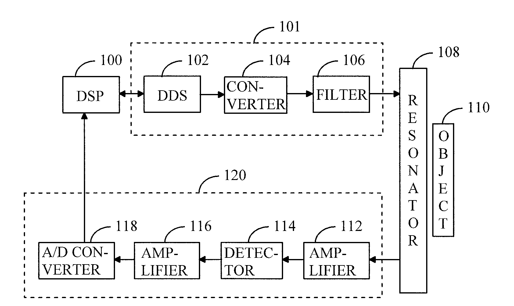
[0029]FIG. 1 shows a measuring device which may comprise a digital signal processing unit 100, a generator 101 generating radio-frequency electromagnetic radiation, a resonator 108 and a receiver 120. The generator 101 may comprise a digital frequency synthesizer 102, a frequency converter 104 and a filter 106. The receiver 120, in turn, may comprise a preamplifier 112, a detector 114, an amplifier 116 and an A / D converter 118, which converts an analog signal to a digital signal.

[0030]The digital signal processing unit 100 may be a computer, such as a PC (Personal Computer) or a signal processor, which comprises a processor, memory and computer software suitable for signal processing. The digital signal processing unit 100 may control at least one parameter in the digital frequency synthesizer 102, which may operate on DDS (Direct Digital Synthesis) principle.

[0031]The frequency synthesizer operating on DDS principle comprises a memory, which stores digital sample values of waveform...


PUM


Abstract

A generator generates radio-frequency electromagnetic radiation to a resonator whose resonance frequency is affected by a characteristic to be measured of an object to be measured. A receiver receives radio-frequency electromagnetic radiation from the resonator and a signal processing unit searches for a resonance frequency of the resonator for measuring the characteristic to be measured. The generator comprises a digital frequency synthesizer for scanning a frequency of radio-frequency electromagnetic radiation to be applied to the resonator over a desired frequency band by using discrete measuring frequencies.

Description

FIELD[0001]The invention relates to a method and a measuring device for measuring an object by radio-frequency electromagnetic radiation.BACKGROUND[0002]Measuring by radio and microwave frequencies may employ as a sensor a resonator that is designed such that characteristics of the object to be measured affect the resonance frequency of the resonator. Because, in general, only one characteristic is measured, the objective is, that at least approximately, the object to be measured has only one factor that affects the resonance frequency. When the frequency of electromagnetic radiation to be applied to the resonator is scanned over a frequency band used for measuring, a resonance frequency may be searched for in the response signal received from the resonator. In order to be able to determine the desired characteristic of an object to be measured by means of the resonance frequency, prior to actual measuring it is necessary to carry out calibration measurements, in which objects to be...

Claims


Application Information

Patent Timeline
IPC IPC(8): G01R27/04
CPCG01B15/02G01N33/346G01N22/04G01N22/00
Inventor JAKKULA, PEKKAVUOLTEENAHO, MIKKOVAISANEN, MIKA
Owner SENFIT
Why Eureka
Try Eureka