
Method and system for correcting oscillator frequency drift

a frequency drift and oscillator technology, applied in the field of oscillators, can solve the problems of difficult auxiliary correction signals, high cost, or both

Inactive Publication Date: 2009-11-12
APPLE INC
View PDF2 Cites 27 Cited by
  • Summary
  • Abstract
  • Description
  • Claims
  • Application Information

AI Technical Summary

Problems solved by technology

However, when the GPS signals are unavailable due to equipment failures or environmental conditions, for example, an auxiliary correction signal must be provided in place of the primary correction signal until the GPS signal becomes available again.
If the auxiliary correction signal is inaccurate during the holdover period, the base station will lose synchronization with the other base stations.
Unfortunately, generating accurate auxiliary correction signals has proven to be difficult, expensive, or both.

Method used


Image

  • Method and system for correcting oscillator frequency drift
  • Method and system for correcting oscillator frequency drift
  • Method and system for correcting oscillator frequency drift

Examples


Embodiment Construction

[0015]The embodiments set forth below represent the necessary information to enable those skilled in the art to practice the invention and illustrate the best mode of practicing the invention. Upon reading the following description in light of the accompanying drawing figures, those skilled in the art will understand the concepts of the invention and will recognize applications of these concepts not particularly addressed herein. It should be understood that these concepts and applications fall within the scope of the disclosure and the accompanying claims.

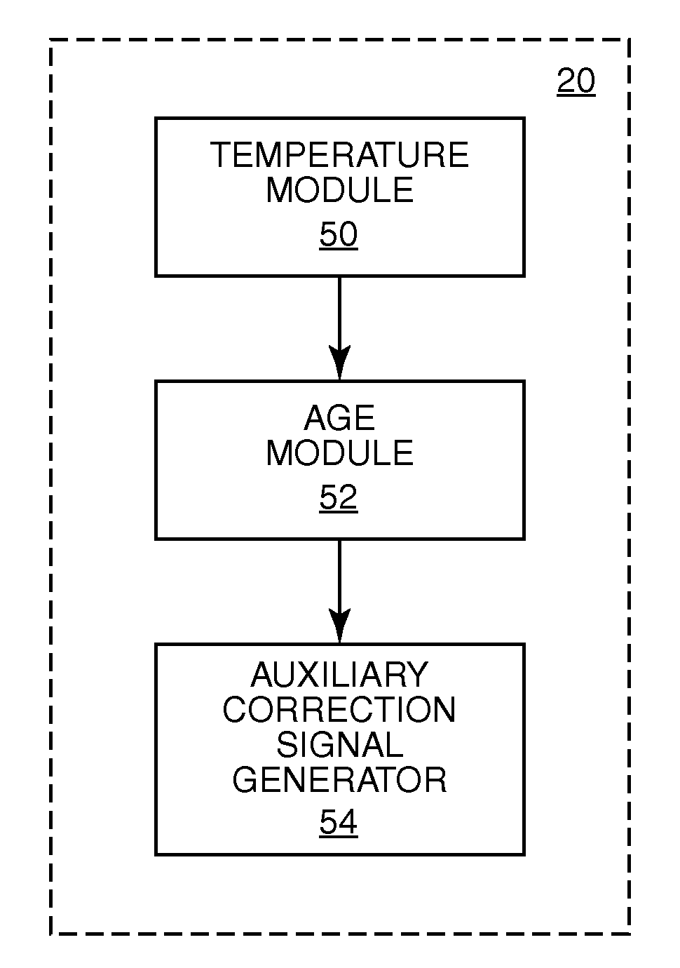
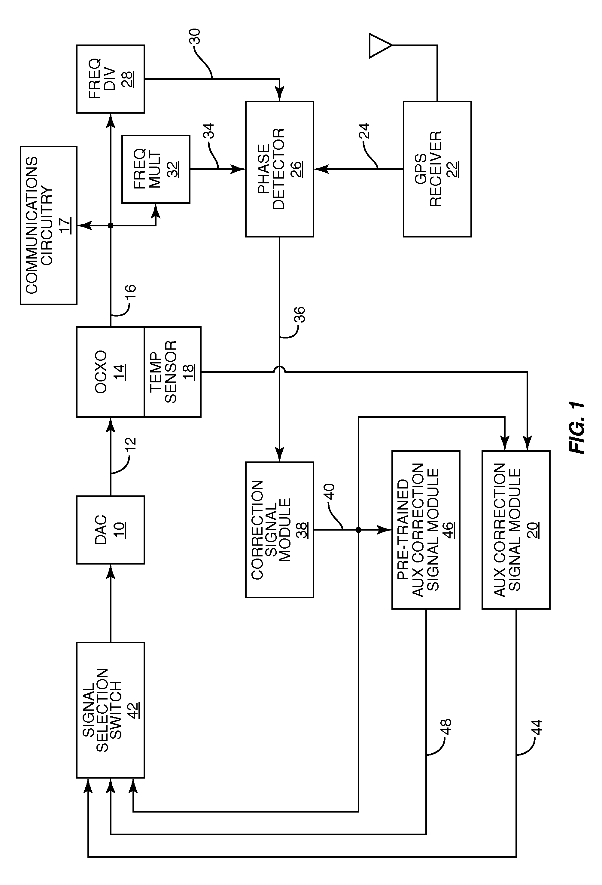
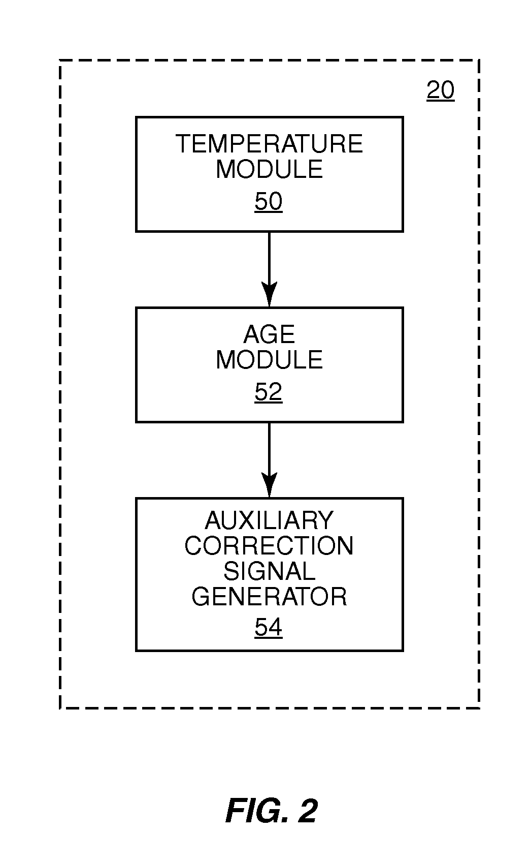
[0016]Referring now to the drawings, FIG. 1 is a block diagram showing an exemplary timing circuit in which the present invention can be utilized. While the present invention is described in the context of a wireless telecommunications base station, it will be apparent to those skilled in the art that the present invention is applicable to any application that benefits from oscillator frequency drift correction when a reference ti...


PUM


Abstract

A method and apparatus for correcting oscillator frequency drift due to crystal aging. Correction signals that reflect a difference between an oscillator timing signal and a reference timing signal over a reference timing signal interval are modeled so that auxiliary correction signals can be generated in the event of loss of the reference timing signal. A temperature curve is generated to model how temperature variation impacts oscillator frequency drift. A rate of frequency drift due to crystal aging is also determined. During loss of a reference timing signal, auxiliary correction signals can be generated to maintain the oscillator at a desired frequency until the reference timing signal becomes available again.

Description

FIELD OF THE INVENTION[0001]This invention generally relates to oscillators, and in particular relates to correcting oscillator frequency drift caused by temperature variation and crystal aging.BACKGROUND OF THE INVENTION[0002]An oscillator provides a timing signal which is used by a telecommunications base station for communications. In certain telecommunications systems it is important that the timing signal provided by a base station is synchronized with timing signals in other base stations. A Global Positioning System (GPS) reference timing signal can be derived from GPS signals that are received by a GPS receiver in the base station to provide a uniform reference timing signal to which oscillators in base stations can be locked, enabling base stations to synchronize with one another.[0003]An oscillator in a base station is responsive to a drive signal. Because the oscillator may drift over temperature and time, the drive signal must be corrected periodically to keep the oscill...

Claims


Application Information

Patent Timeline
IPC IPC(8): G01R23/00
CPCH03L7/093H03L1/022H03L7/146
Inventor NICHOLLS, CHARLES W. T.WU, PHILIPPE
Owner APPLE INC
Learn More