Temperature measuring circuit

A temperature measurement circuit and circuit technology, applied in thermometers, measuring devices, measuring heat, etc., can solve problems such as inability to eliminate the influence of wire resistance, single test object, and data jumps

Active Publication Date: 2008-04-30
SHENZHEN MINDRAY BIO MEDICAL ELECTRONICS CO LTD
View PDF1 Cites 26 Cited by
  • Summary
  • Abstract
  • Description
  • Claims
  • Application Information

AI Technical Summary

Problems solved by technology

[0010] 1. The lead wires at both ends of the sensor require the same material and length to eliminate the influence of wire resistance from the perspective of non-circuit design, but sometimes the same material and length cannot be satisfied, so the influence of wire resistance cannot be eliminated
[0011] 2. Although it is possible to switch channels, the test object is relatively single and can only be the same sensor, which is not suitable for the measurement requirements of multiple sensors.
[0012]3. When performing multi-channel temperature measurement, it is necessary to switch the analog switch. Ideally, the channel that has not been switched is considered to be floating and the current is zero. However, In fact, there will be a leakage current. After the leakage current flows through R0, it will directly affect the sporadic jump of the signal size at the input terminal of U2, which will eventually lead to different measurement data of the same channel in the process of channel switching. jump

Method used


Image

  • Temperature measuring circuit
  • Temperature measuring circuit
  • Temperature measuring circuit

Examples


Embodiment Construction

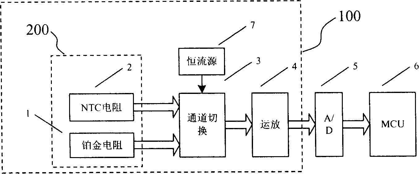
[0038] The block diagram of the temperature measurement circuit of the preferred embodiment of the present invention is as figure 2 As shown, the temperature measurement circuit 100 includes a temperature sensor circuit 200 , a channel switching device 3 , an operational amplifier 4 and a constant current source 7 . The whole temperature measurement system also includes A / D acquisition circuit 5 and MCU 6 .

[0039] The temperature sensor circuit 200 may include multiple channels, the resistance of the temperature sensor will vary with the temperature, the channel switching device 3 is used to switch between multiple sensor channels, and the current of the constant current source 7 will flow through the switched The sensor converts the resistance of the sensor into a voltage for measurement, and the voltage value will be input to the operational amplifier 4 to realize the amplification processing of the weak voltage signal of the sensor, and the A / D acquisition circuit 5 will...


PUM


Abstract

The invention discloses a temperature measurement circuit, which includes a temperature sensor circuit, a constant current source and a first operational amplifier. The negative pole of the power line drawn from the second end and the positive pole of the sensing lead and the negative pole of the sensing lead drawn from the first and second ends of the temperature sensor respectively, the constant current source is connected to the positive pole of the power line of the temperature sensor circuit, and the positive and negative poles of the first operational amplifier The negative input end is respectively connected to the positive electrode of the sensing lead and the negative electrode of the sensing lead of the temperature sensor circuit, the output end outputs a voltage-temperature curve, and the negative electrode of the power line of the temperature sensor circuit is coupled to the ground. The invention adopts a four-wire system, so that the positive and negative input ends of the first operational amplifier are respectively connected to the positive electrode of the sensing lead and the negative electrode of the sensing lead of the temperature sensor circuit. The effect of wire resistance on the output result.

Description

【Technical field】 [0001] The invention relates to a temperature measuring circuit, in particular to a temperature measuring circuit which converts a temperature signal into an electric signal through a temperature sensor, and then performs A / D sampling and processing on the electric signal. 【Background technique】 [0002] In many modern products, accurate measurement of temperature is required. The current temperature acquisition methods include two-wire system, three-wire system, single-channel and multi-channel temperature measurement methods. Among them, the three-wire multi-channel temperature is a relatively new temperature acquisition technology solution. The Chinese patent with the patent number 03263202.9 and the invention name "A Thermal Resistance Temperature Measurement Circuit" discloses this technology. The schematic diagram of its principle is as follows figure 1 shown. This scheme uses a single constant current source to work, U1 is a voltage follower, and U...

Claims


Application Information

Patent Timeline
Patent Type & Authority Applications(China)
IPC IPC(8): G01K7/16G01K7/18G01K7/21G01K7/22G01K7/25G01K7/42
Inventor 夏禹刘奇林朱星才
Owner SHENZHEN MINDRAY BIO MEDICAL ELECTRONICS CO LTD
Why Eureka
Try Eureka