Beam adjusting device

a beam angle and beam technology, applied in waveguides, antenna details, antennas, etc., can solve the problems of mechanical tolerance, relatively low influence on signal phase, and thus beam angle,

Inactive Publication Date: 2009-11-12
INTEL CORP
View PDF8 Cites 13 Cited by
  • Summary
  • Abstract
  • Description
  • Claims
  • Application Information

AI Technical Summary

Benefits of technology

[0006]It is an object of the present invention to provide a device for adjusting the beam direction of a beam radiated from a stationary array of antenna elements that solves the above mentioned problem. In particular, it is an object of the present invention to provide a device for adjusting the beam direction of a beam radiated from an array of antenna elements that is capable of ensuring that an intended beam tilt angle actually results in a set beam tilt angle corresponding to the intended beam tilt angle.

Problems solved by technology

A problem with the device described in WO 96 / 37922 is that the influence on the signal phase, and thus the beam angle, is relatively low.
A problem with the device described in WO02 / 35651 is mechanical tolerances.
A problem with both of the above described solutions is that it is difficult to ensure that an intended beam tilt angle actually results in a set beam tilt angle corresponding to the intended beam tilt angle.

Method used


Image

  • Beam adjusting device
  • Beam adjusting device
  • Beam adjusting device

Examples


Embodiment Construction

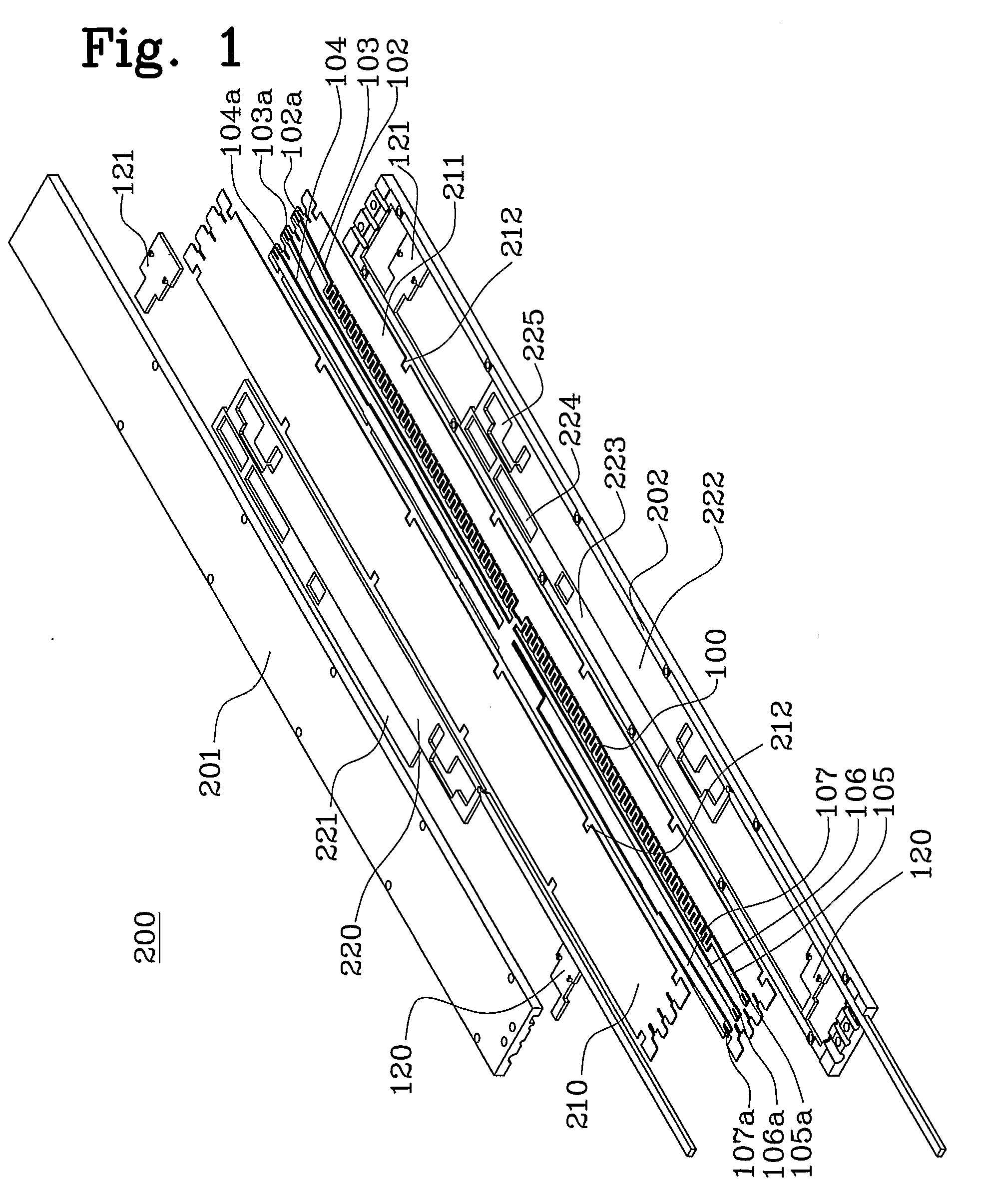
[0037]In FIGS. 1 and 2 are shown an exemplary device 200 with which the present invention may be utilised. In FIG. 1 is shown an exploded view of the device for adjusting the beam direction of a beam of an antenna. The device 200 comprises an elongated box-like housing consisting of an upper part 201 and a lower part 202, constituting ground planes. A feed line structure 100 is also shown. Each feed line segment 102-107 of the feed line structure is connected to an associated feed connection terminal 102a-107a. The feed connection terminals 102a-106a are connected, e.g. by coaxial cables (not shown), to associated antenna elements or sub-arrays, e.g. pairs of antenna elements, arranged in a stationary array, normally a linear row, in an antenna, e.g. a base station antenna. In use, the feed connection terminal 107a is connected, e.g. by a coaxial cable, to transceiver circuits (not shown), e.g. included in a base station of a cellular mobile telephone system.

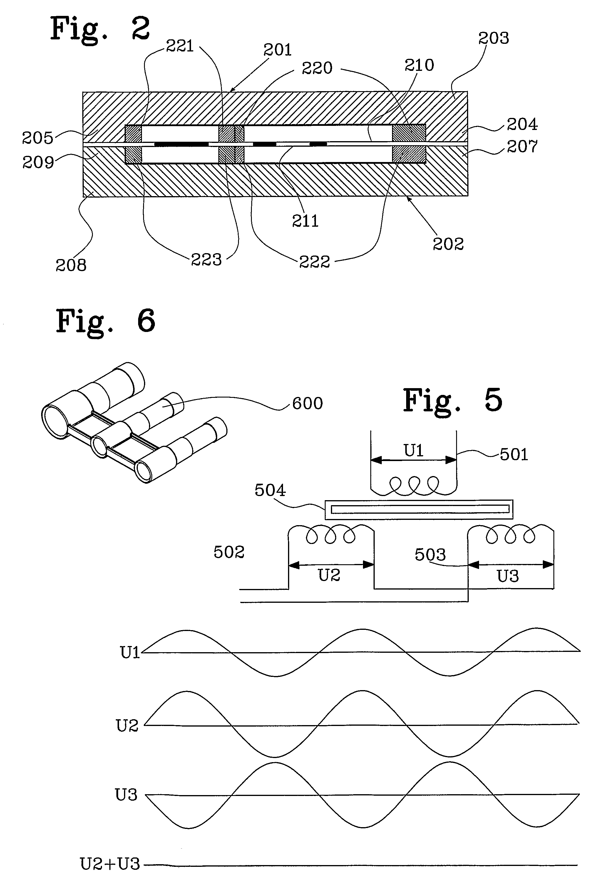
[0038]In FIG. 2 is shown...


PUM


Abstract

The present invention relates to a device for adjusting the beam direction of a beam radiated from a stationary array of antenna elements, wherein at least two antenna element feed points are coupled to a common signal source via a feed line structure having a source connection terminal to be connected to said source and at least two feed connection terminals to be connected to said antenna element feed points, said feed line structure being at a distance from and in parallel to a fixed ground plane on at least one side of said feed line structure, wherein a movable element is located adjacent to said feed line structure so as to change the signal phase of signal components being transferred between said source connection terminal and the respective feed connection terminals, said movable element being movable for effecting a controlled phase shift of said signal components so as to adjust said beam direction. The device is provided with detection means for detecting the absolute position of the movable element.

Description

FIELD OF THE INVENTION[0001]The present invention relates to a device for adjusting the beam direction of an antenna. More particularly, the device is of the kind defined in the preamble of claim 1.[0002]The present invention also relates to an antenna control system for adjusting the beam direction of an antenna. More particularly, the system is of the kind defined in the preamble of claim 24.RELATED ART AND BACKGROUND OF THE INVENTION[0003]Such devices are previously known from the documents WO 96 / 37922 (Allgon AB) and WO02 / 35651 A1 (Allgon AB). The device known from WO 96 / 37922 comprises a feed line structure integrated with a stationary array of antenna elements so as to enable adjustment of the direction of the beam radiated from the array. The feed line structure includes a feed conductor line pattern disposed on a fixed dielectric carrier plate at a distance from and in parallel to a fixed ground plate. The feed line structure is disposed on the carrier plate surface facing a...

Claims


Application Information

Patent Timeline
Patent Type & Authority Applications(United States)
IPC IPC(8): H01Q3/32
CPCH01P1/184H01Q3/32H01Q3/005H01P3/087
Inventor MAKINEN, JARMOEKERVIK, OLOVAKESSON, DANIELLILJEVIK, TORDDAGERHAMN, JOHANOSTLIND, ERIK
Owner INTEL CORP
Why Eureka
Try Eureka